")
")
 |
While building up my remote station, i was looking for a solution to control one or 2 azimuth only rotators via the Internet. There are several solutions and i finally adopted the K3NG rotator project i already used for a rotator controller connected via USB to my computer. |
I used an Arduino UNO but the code eats almost all memory and it should advisable to use a Arduino MEGA board as recommended by K3NG.
Nevertheless, limiting the options to a minimum (no LCD, etc...) and commenting or uncommenting the following lines in the rotator_features.h file like below to save some memory makes it work on a UNO board :
//#define DEBUG_DUMP
#define OPTION_SAVE_MEMORY_EXCLUDE_REMOTE_CMDS
Software configuration:
Beside the normal settings you have to make for your particular rotator, you need to add the Ethernet protocol to your Arduino rotator interface.
The first file that has to be configured is the rotator_features.h, by uncommenting and setting your own parameters the following lines :
#define FEATURE_ETHERNET
#define FEATURE_MASTER_WITH_ETHERNET_SLAVE
The next file to configure is the rotator_settings.h in setting your own IP parameters :
#define ETHERNET_MAC_ADDRESS 0xAA,0xBB,0xCC,0xDD,0x00,0x01
#define ETHERNET_IP_ADDRESS 192,168,1,173
#define ETHERNET_IP_GATEWAY 192,168,1,1
#define ETHERNET_IP_SUBNET_MASK 255,255,255,0
#define ETHERNET_TCP_PORT_0 23
#define ETHERNET_TCP_PORT_1 24
The Ethernet board is using pins 10,11,12 and 13 for the Ethernet interfacing. Pin 4 is reserved fot the onboard SD card.
I used pin A5 for the potentiometer analog input. Pins 7, 8 and 9 for the CW, CCW and BRAKE commands.
The rotator_pins.h file has to be modified accordingly.
#define rotator_analog_az A5
#define rotate_ccw 7
#define rotate_cw_ccw  8
#define brake_az 9
After that, you can compile the k3ng_rotator_controller.ino file with the Arduino IDE and upload it the the Arduino board.
How to use it :
With a remote PC on which the transceiver and rotator are physically connected, there is no real difficulties.
The interface is connected to the PC thru a USB port which appears like a COM port.
A VNC software or Windows remote desktop is used.
In order to use the interface with a logging or contest software on a local computer with a remote transceriver and rotator, you need to establish a Telnet connection between the computer and the Arduino.
The easiest way to do that is to use a software that does this natively, like PSTrotator by YO3DMU which is a masterpiece of software!
The more universal way is to interface the rotator and transceriver on the local computer via virtual COM ports.
This is done by using a TCP client that transforms the commands sent to your serial port into a TELNET command to the TCP server (your Arduino board). I used the free 32bit emulator VSPE and/or com0com for doing that.
TCP client with VSPE :
1) Create a new device using the "Create a new device" button and select "Connector'. Choose a new virtual port number, for example COM3.
2) In the same way, create a new device by selecting "TcpClient". Enter the "Remote TCP host address" and "Remote TCP port" you defined in the Arduino rotator_settings file.
The "Source serial port" should be the one you create just before. I also checked the DTR/DSR box.
If all is fine and after emulation start, you should see a new COM port in your Windows device manager and logging software. You normaly can use your remote rotator like if it would be directly connected to your computer.
TCP client using com0com
You can also use the com0com package. Once installed, with the "Setup command prompt", create ( for example if COM5 is free ) COM5<->CNCB0 virtual COM port pair (see com0com's ReadMe.txt for more info)
command> install 0 PortName=COM5,EmuBR=yes -
Start the com2tcp-rfc2217.bat on CNCB0 port. You can create a batch file for this, with at least the following line :
com2tcp-rfc2217 \\.\CNCB0 your.Arduino.server.ip 23
Run the bacth file and com2tcp will start and redirect the virtual serial port COM5 to the rotator Telnet server via TCP.
Using PSTrotator :
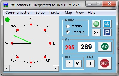
Open the "Communication" menu, select "TCP Client". In the TCP Client setting window and Azimuth field , enter the IP address set in the rotator_settings file. You should be able to connect to the Arduino board and get a green button in front of the azimuth line.
Open the "Setup" menu and select "Start as TCP Client", and choose an appropriate" Refresh rate".
From now, you should be able to remote your rotator.
Using WTrotator :
You can test the result with the WinTest rotator interface: WTrotator. Use at least WT rotator version 1.5 downloadable here : http://download.win-test.com/wtRotators/bin/wtRotators-1.5.exe
With the "Controllers" menu, add a controller selecting K3NG.
Select the previous virtual created COM port and add at least on antenna, and you're QRV !
Enter a name for this controller and select at least one antenna.
Using Logger32
In the rotor setup window, use the above created port COM number, 9600,N,8,1 and GS232A in "rotor type".
In PSTrotatorAz, select Logger32 from the "Tracker" menu.
Ctrl+A and Alt+A rotate the rotor in the "short path" or "long path" direction.
As a bonus, with PSTrotator, you can park your rotator in a safe direction when the wind speed is higher than a trigger value. This is done with the menus "Setup" + "WX setup" and "Wx information".
I use my local WX station described here.