")
")
To be finished...
Some years ago, i developed my own rotator interface with a PIC 18F452. In a need of another interface, i was unable to find my software sources of this project, lost somewhere in the computer Walhalla ! So, i looked for a finished project to build, and found the K3NG Arduino rotator project.
It looked very complete and having some recent experiences with the Arduino, i decided to give it a try.
What i needed :
- Only azimuth drive
- 2 lines LCD display (as i had several of them)
- Eventualy 2 buttons CW + CCW to drive the rotator
- Running on an Arduino Uno (as i had several)
After reading the documentation (that could be better) i found my way out, and after some solder smoke + cut and try configurations, i managed to display the azimuth on a 2 line LCD. I tested it with a 500 Ohm potentiometer to simulate the rotator.
I then designed a shield that would plug into the Arduino Uno and everything worked as predicted !
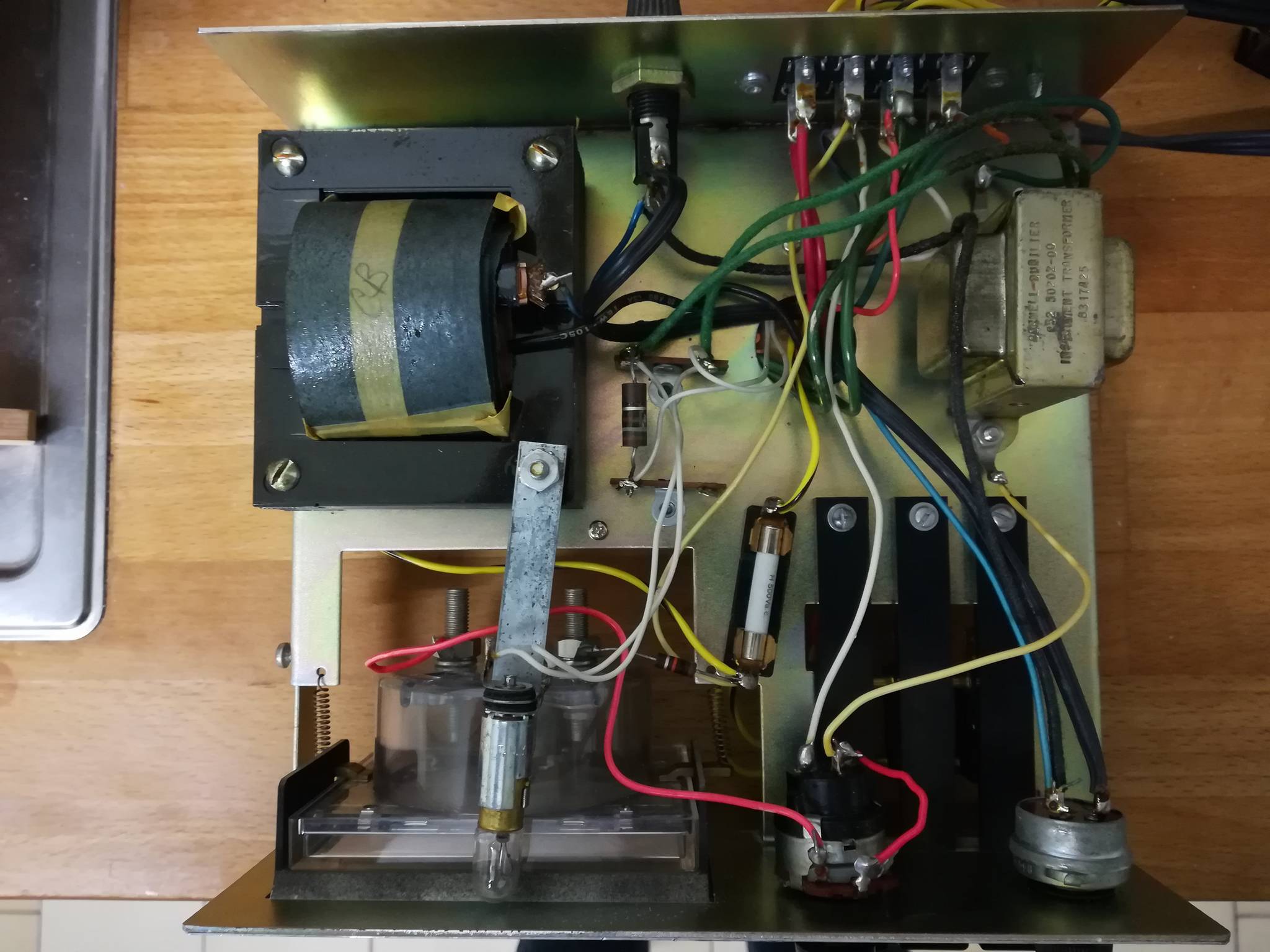
Now came the time to interface it with my old rotators, a HAM IV and a CD 44. Both have the same design and a major drawback : the potentiometer shaft is grounded and a lot of current is drawn through the ground via the motor and brake, inducing a lot of problems when you try to measure the voltage coming from the direction potentiometer.
The best solution would be to electricaly insulate the shaft from ground and have a separate wire for it. One could add an additionnal wire on the cable, which already has 8 wires, or move the phasing capacitor from the control box to the rotator, saving 2 wires that could then be re-used.
But i didn't want to do all this, and i finally managed to handle this problem correctly. I first replaced the primitive 12V supply in the control box with a 12V integrated regulator, both + and - lines being isolated from ground. Then, i filtered the signal coming from the direction pot. with an RC filter. The result is good enough for my needs.
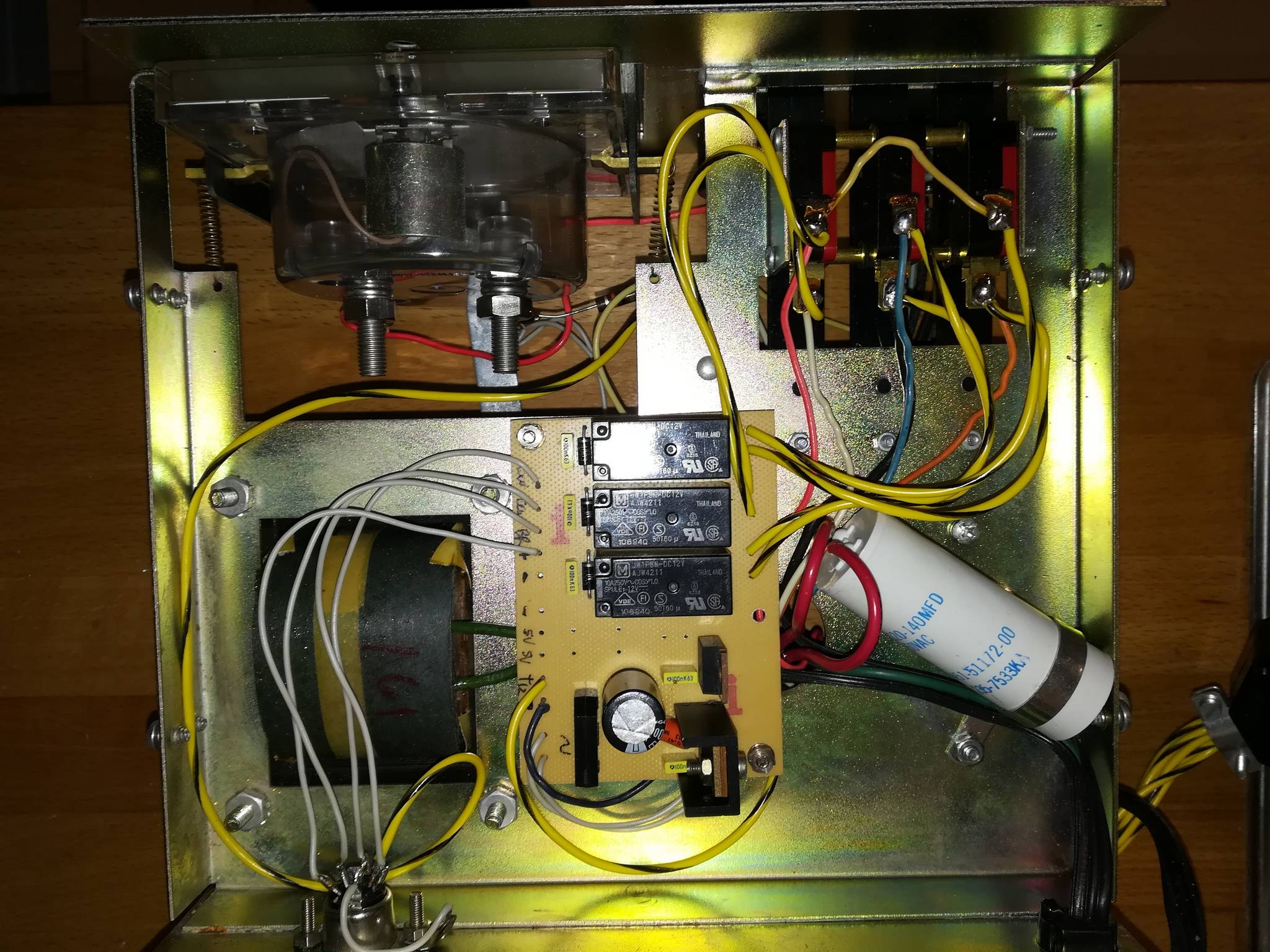
Control box modifications
Wanting to still use the control box, i had to modify it to be compliant with the interface. The modifications made on the control boxes will allow the rotator + box to be used as the original.
Unpluging the cable to interface will leave the box as untouched.
I did the following :
- Removing the original 12V supply and wirings
- Adding a new board with +12V supply and 3 relays to drive the motor and brake.
- Adding a DIN 5 pin + ground connector on the rear (or any other connector allowing at least 6 poles)
- Rewiring the box.
The 7812 regulator can also be wired in lieu of the Zener diode. The relays can be glued to the chassis and "air" wired. A PCB is not needed at all...
I replaced the internal 12V supply originaly "stabilized" by a Zener diode with a more stable 12V coming from a 7812 regulator. This stable voltage drives the galvonometer and is fed into the interface. A variable resistor on the interface will drop this 12V to a maximum of 5 V to be compatible with the Arduino input.
The minus line of the 12V supply in the control box is FLOATING and should not have any reference to the ground !
The 3 relays are supplied with a 12V source coming from a separate external supply in order to separate completely the grounds. The single pole contacts are wired in parallel with the 3 pushbuttons ( CW, CCW, BREAK)
 |
 |
Shield construction
I found that the easiest way to build the interface was to design a shield on which Arduino Uno could be plugged in. I used KICAD to design the PCB and took care to use only a single face PCB that can be made by a hobbyist.
Meanwhile i designed an universal interface for which i still have some boards left in someone is interested ! See my other article for an universal K3NG board !
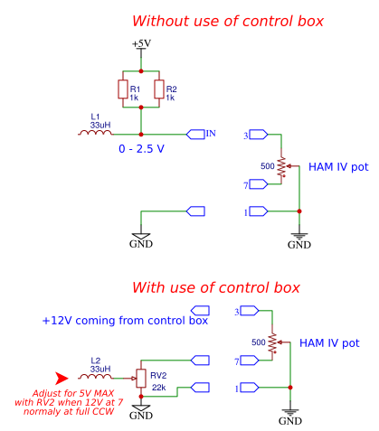
The LCD + backlight is driving some current (170mA) on my large display, so i added a 5V /1A regulator on the shield. My rotator control boxes have a 12V supply and the voltage on the rotator potentiometer varies from 0 to 12V, so i added a adjustable resistor to bring this voltage down to 0-5V to stay within the Arduino limits.
The board also provides a way to supply a 5V to the potentiometer line through a 500 Ohm resistor (or anything other value according to your need), so that the circuit can be modified to use only 2 wires of the potentiometer and not use the control box internal galvanometer and all the 12V supply. Voltage varies then from 0 to 2.5V, and the 22k variable resistor can be ommited.
 |
The cable between the interface and control box has two 5 poles DIN 180° connectors. It has 5 wires + shield for GROUND ! Both sides must be grounded ! Or use any other 6 pole connectors.
The 12V supply in the HAM IV control box can't be used to supply the relays, as this supply is completely isolated from ground. So, the relays are supplied via the external 12V supply that powers the Arduino Uno. Each relay is drawing about 50 mA, so 100 mA are needed when 2 relays are powered (brake + direction relays). A 12V/1A wall power supply with a 5.5mm diameter with 2.1mm barrel plug will do the job to supply the complete interface boards + relays.
The male pins soldered on the shield and that will plug into the Arduino Uno, should be longer that normal pins. Otherwise the shield PCB tracks can touch the Arduino components ! I used 19mm long pins i had.
K3NG configuration files
The following parameters have to be changed to be used with my project :
in rotator_features.h
#define FEATURE_YAESU_EMULATION
#define LANGUAGE_ENGLISH
#define FEATURE_AZ_POSITION_POTENTIOMETER
#define OPTION_SAVE_MEMORY_EXCLUDE_REMOTE_CMDS
#define DEFAULT_DEBUG_STATE 0
in rotator_pins.h
#define rotate_cw 6
#define rotate_ccw 7
#define brake_az 5
#define rotator_analog_az A0
#define lcd_4_bit_rs_pin 9
#define lcd_4_bit_enable_pin 8
#define lcd_4_bit_d4_pin 13
#define lcd_4_bit_d5_pin 12
#define lcd_4_bit_d6_pin 11
#define lcd_4_bit_d7_pin 10
in rotator_settings.h
#define LCD_COLUMNS 16
#define LCD_ROWS 2
#define LCD_AZ_ONLY_HEADING_ROW 1
#define LCD_HEADING_ROW 2
Adjustment and calibration
The only adjustments needed are the LCD contrast with VR1 and the maximum voltage on the Arduino input pin.
Before any power is applied, the VR2 pot. should be adjusted so that the cursor is at minimum (close to ground).
During development, i had completely incoherent azimuth readings and that drove me crazy ! I finally discovered that on the first Uno board i used, the 5v regulator on the Arduino delivered only 4.21V !! So the maximum analog voltage that could be read by the Arduino was limited to 4,21 V, and i have close to 5V coming from the rotator... :-(
So, as a precaution, you also need to measure the voltage of the 5V supply of the Arduino. This voltage will be the maximum that can be measured by the ADC converter in the Arduino. Turn your rotator fully clockwise and counterclockwise and measure the voltage variation between ground and pin 4 of the DIN connector and leave it on the postion where you have the maximum voltage. (generally fully CW)
Then, adjust VR2 to have on the ADC input (on R8/D1) a voltage lower by a 100mV than the voltage measured on the Arduino 5V supply.
You can then use the YAESU calibration procedure with the O and F commands. To do that, connect the USB port and find out what COM port is used.
Use a terminal software (i use Realterm) and configure it for 9600 bauds, no parity, 8 bits length, 1 stop bit and no handshake.
Press "C" and RETURN, the software should return the current azimuth. If not, check what's wrong before continuing...
Press "O", and follow instructions dsiplayed on screen. (turn fully CCW and press ENTER).
Press "F", and follow instructions dsiplayed on screen. (turn fully CW and press ENTER).
Something which is (at time of writing this) not documented and drove me crazy were a new set of commands that allow to change some configuration parameters via the USB port ! These parameters are overwriting the one in the configuration files !
\Ix[x][x] - set az starting point
\I - display the current az starting point
\Jx[x][x] - set az rotation capability
\J - display the current az rotation capability
\Kx - force disable the az brake even if a pin is defined (x: 0 = enable, 1 = disable)
\K - display the current az brake state
\Q - Save settings in the EEPROM and restart
So, you NEED to change the AZ starting point, the AZ rotation capability and the AZ brake state via a terminal connected to the USB port, even if you modified them in the configuration files !!
I used :
/I180
/J360
/K0
After that, everything runned just fine...
You're done !