")
")
 A friend of mine who bought a cheap Kenwood TL922 power amplifier asked me to repair it and to bring some modifications in order to improve the security. This is the fruit of my works...
So, before any tests i have made the following modifications :
- Step-start
- Filament transformer protection
- HV protection agiainst internal valve flash
- Zener diode substitution
- PTT circuit modification ofr low voltage switching
- RF relay substitution
- RF stability improvement
- Symetrical tube feeding
WARNING ! These modifications are NOT for newcomers or untrained people. You MUST have some experience in HIGH VOLTAGES equipments. HV can kill and introduce heavy damages to your amplifier !
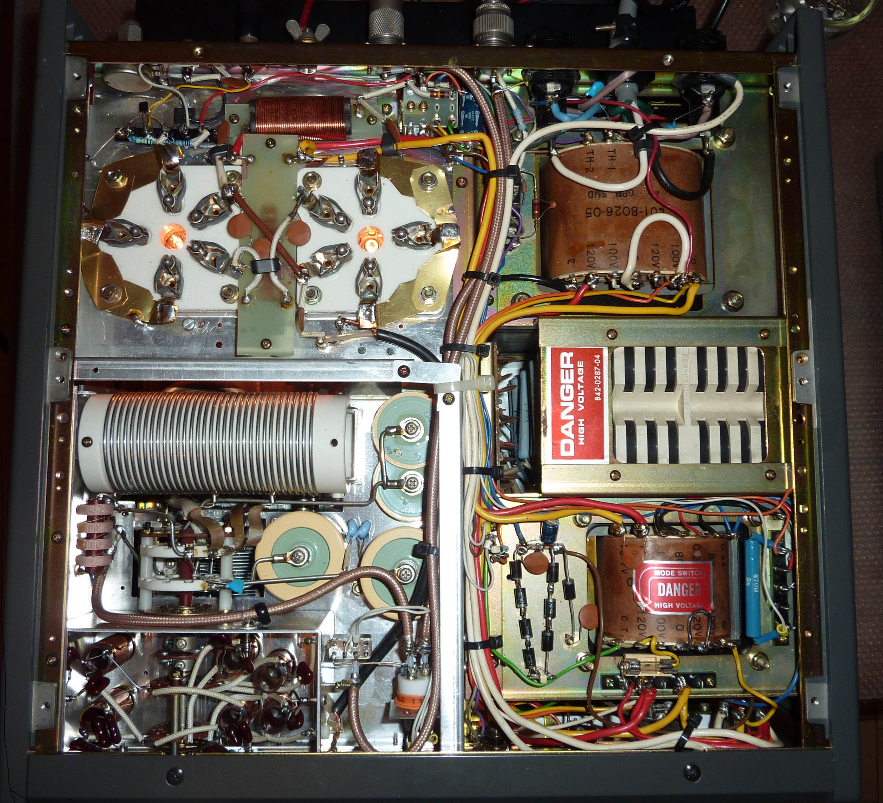
At power on at sellers home, the amplifier was blowing the main fuse in the electrical panel, so it was out of question to power it at home ! A quick look in the amplifier made me discover that a RFC L8 and a resistor R47 were burned around one tube socket. The Zener diode D2 was also shortened which confirmed the diagnostic of a tube flash.
Soft-start
My friend having bought a ready made board, but for a Heathkit SB201, i used it here in the TL922. The main problem was to find a place where to insert this board ! I finaly found that the most interesting place was at the back of the amplifier where the 2 voltage selector terminal boards are housed. They are not used anyway, once you have selected your main supply voltage.
I removed both terminals with the connected wires and rewired the 2 transformer primaries. by adding some heavy gauge wires.
T2, the filament transformer has been rewired for 240V, in order to reduce the filament voltage which is often too high.
T1, the HV transformer has been rewired for 220V, in order to get a bit more HV.
By luck, the board fits perfectly in place, 2 original screws are used with 2 plastic spacers. The 2 wires going to the center pole of both 15A fuse holders are unsoldered, lengthned with heavy gauge wires to the input of the soft-start board. Don't forget to isolate the solder joints !
The outputs are wired with the same cable colors to the poles left free on the fuses. The board is supplied with 100V coming from the HV transformer, which acts as an auto-transformer. I put a red wire from the "F" hole to the 100V pole of the HV transformer.
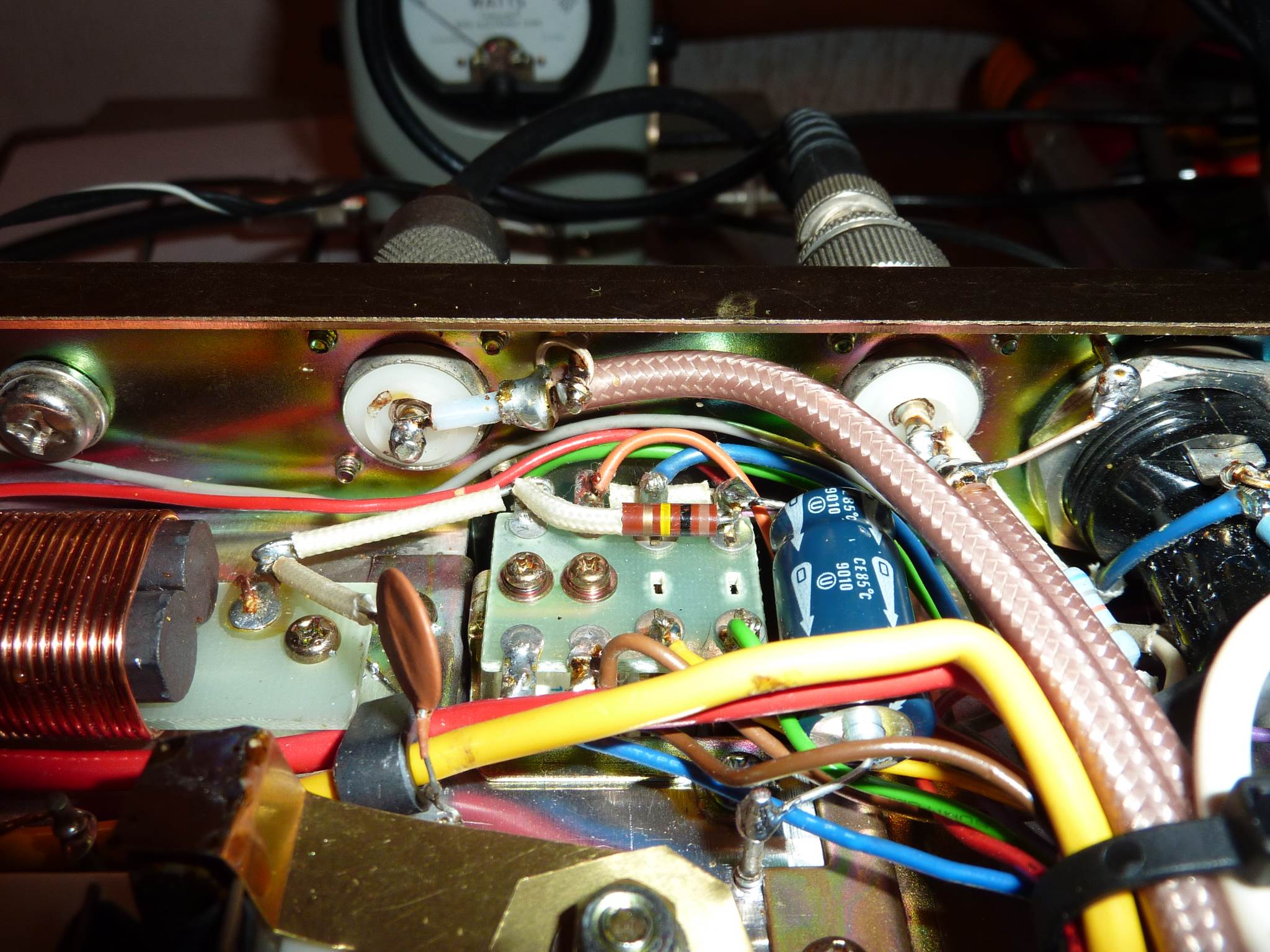
Filament transformer protection
 In case of serious problem on one of the tubes, a filament can go short, and the T2 filament transformer being not fused (apart the 15A fuses), can burn !
 HV protection against internal tube flash
 If a tube should have, for any reason, an internal flashover, the HV power supply could have some damages as well as the polarization diode(s).
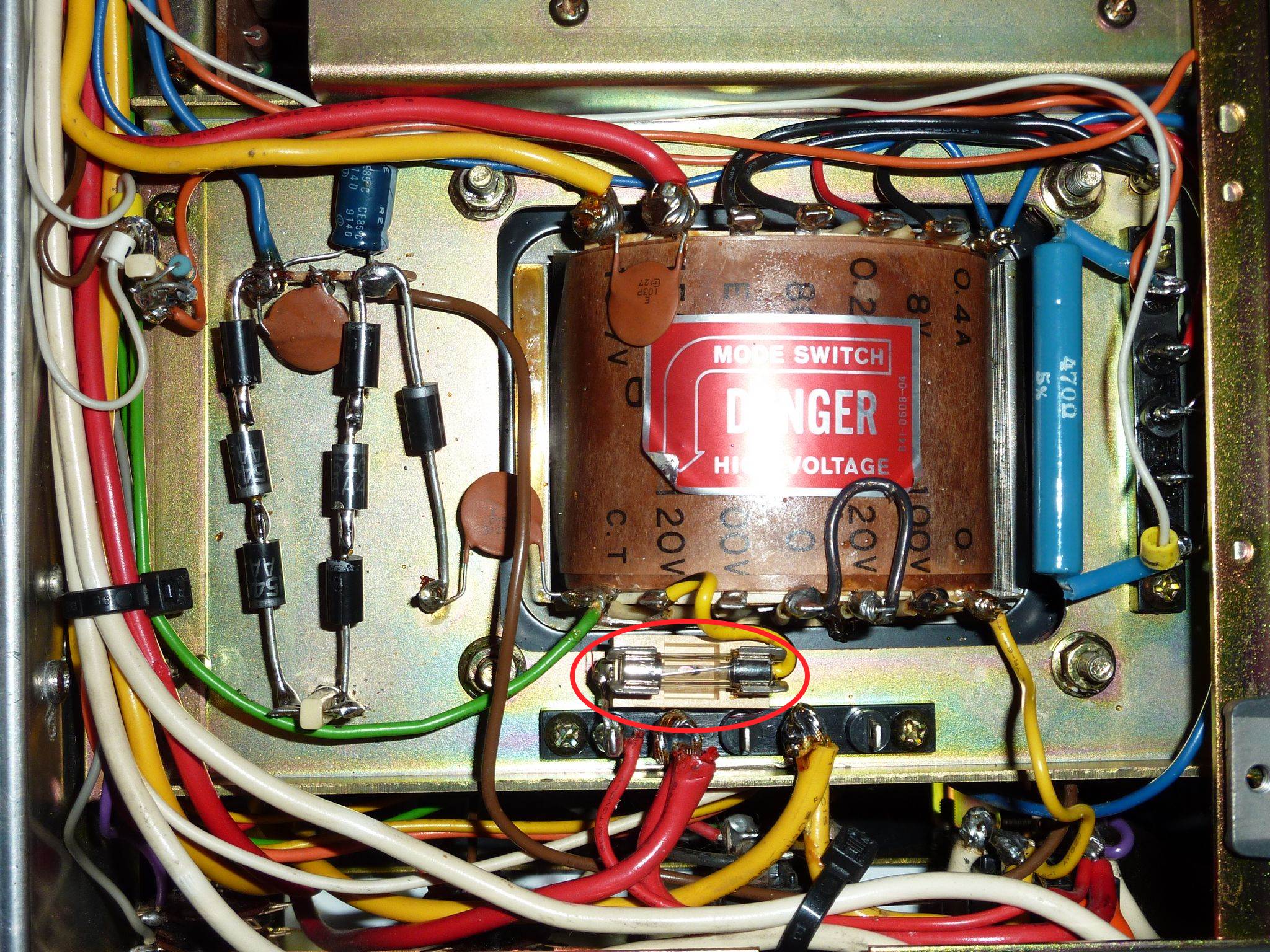
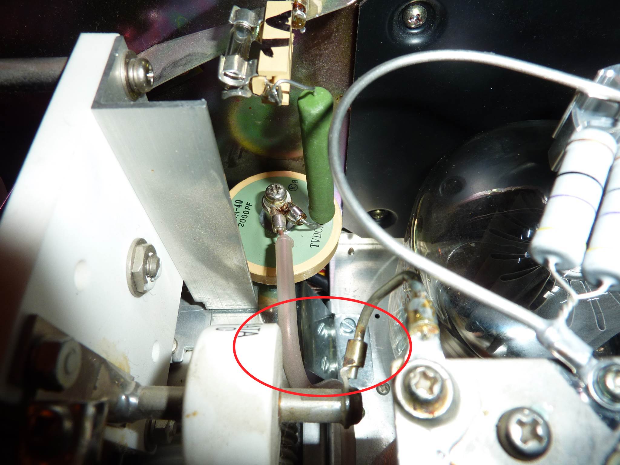
Adding a 10 Ohm resistor and a 1A FAST fuse in series with the HV line protects both the tubes and the power supply. I did that after the interlock and in substitution of L2.
More details on the picture.
Zener diode substitution
 The idle current Zener diode D2 is a major failure source in this type of amplifier. Another drawback is that this diode has a fixed voltage value and idle current can't be adjusted.
I sustituted this diode with a series of high duty diodes. Kenwood recommends an idle current of 200 mA in SSB and 100 mA in CW. I had to use seven 1N5408 diodes to do that. Adding a diode reduces the current and inversely.
I removed the original diode + the mounting bracket and re-arranged the original soldering pole. I also added a new soldering pole and wired like shown on the picture.
Note that the meter protection diode D7 has been replaced as well...
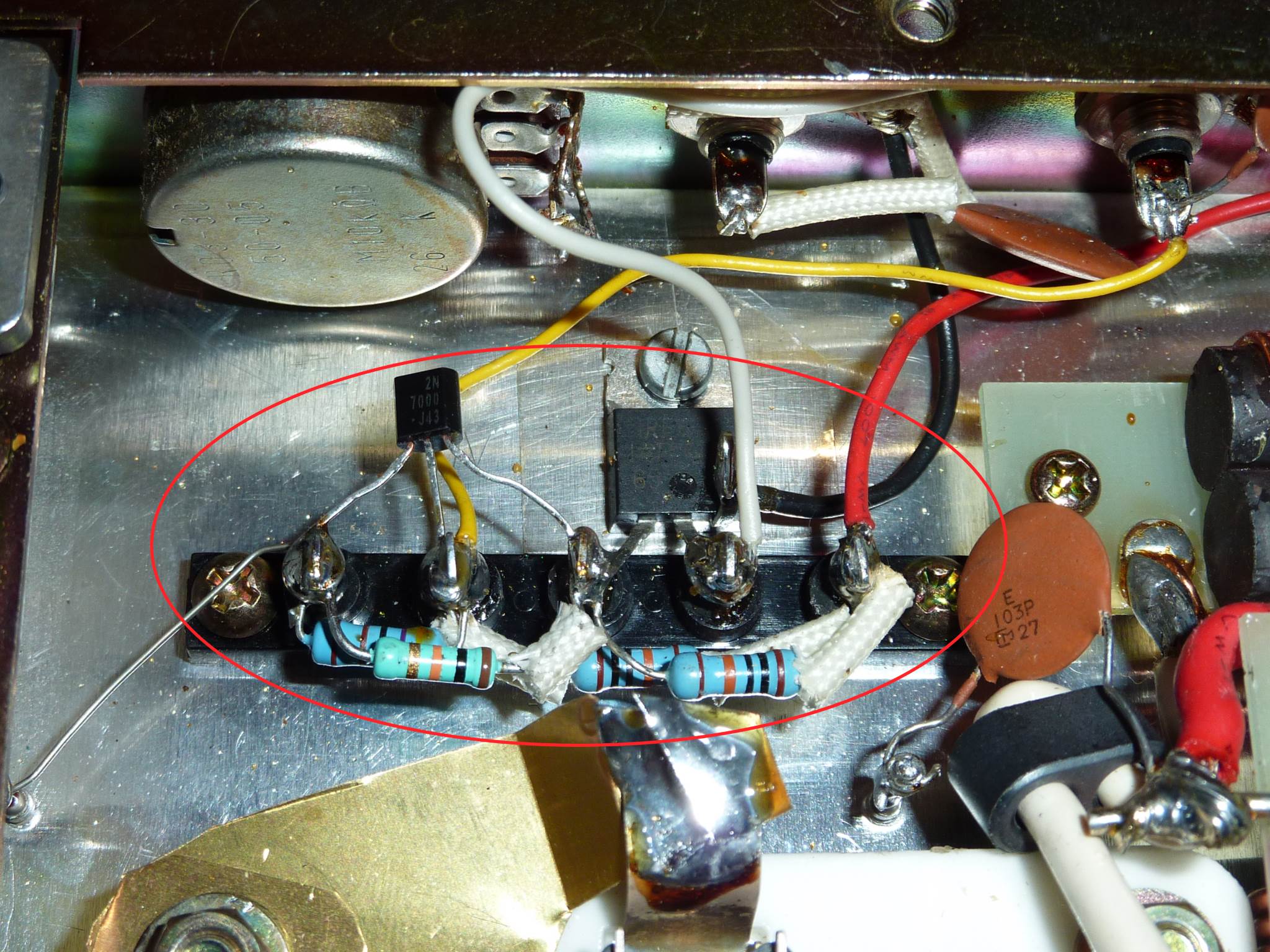
PTT circuit modification
The relays RL1 and RL2 are powered with a 100V DC voltage, the T/R switching is done by grounding the "cold side" of this relays. These 100V are then present at the RL-CONT connector. The switched current is about 150 mA and many modern transceivers do not tolerate these conditions !
The modification consists in adding transistors in order to switch a low voltage/current.
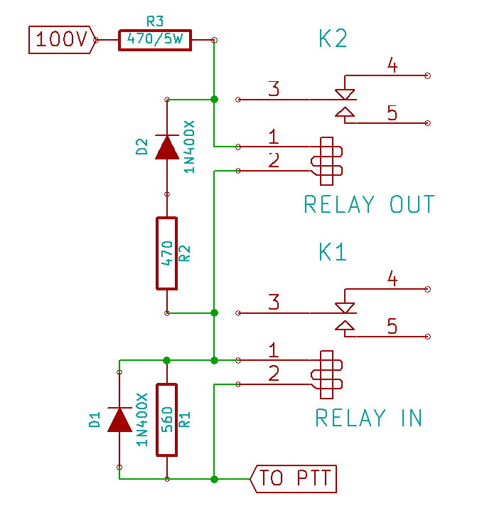
I removed all ALC components soldered on the solder terminal and re-used it to wire the following diagram.
 |
 |
| The circuit | Diagram |
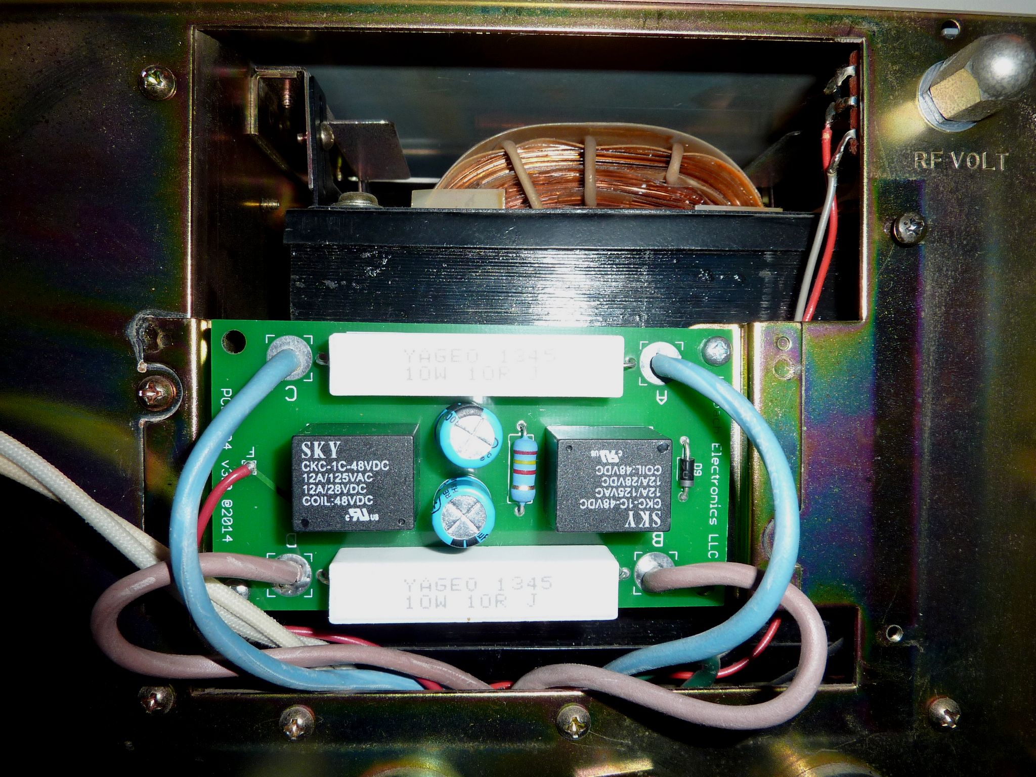
RF relay replacement
The original RF relay RL1 is a heavy, loud and slow 100V relay The following modification replaces this relay with 2 smaller and faster one .The output relay is a vacuum one and the input a small REED one.
My friend already bought two 26.5V relays for this purpose. I had to modifiy the powering circuit to have this voltage on each relay. The resistors are introducing different fall times, in order to have no hot switching. I removed all coaxial cables and used Teflon insulated cables, they are easier to handle.
There is another modification that can be found for a full break-in switching. I didn't do it.
If a had to do the modification for myself, i would buy 12V relays and power them in parallel with a 12V supply made with the 10 V AC transformer.
 |
 |
 |
| RF connectors rewired | RF relays | Diagram |
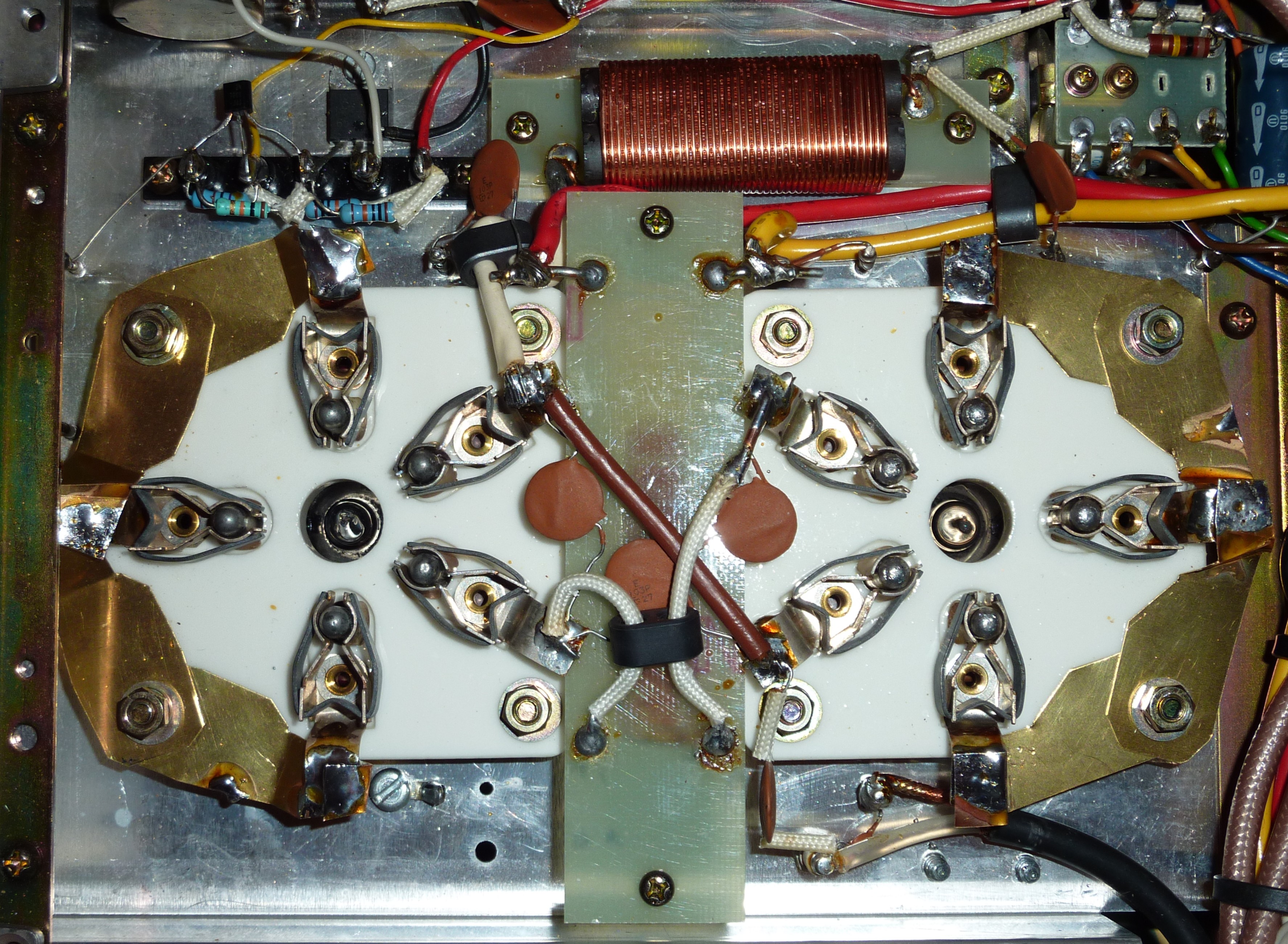
Stability improvement
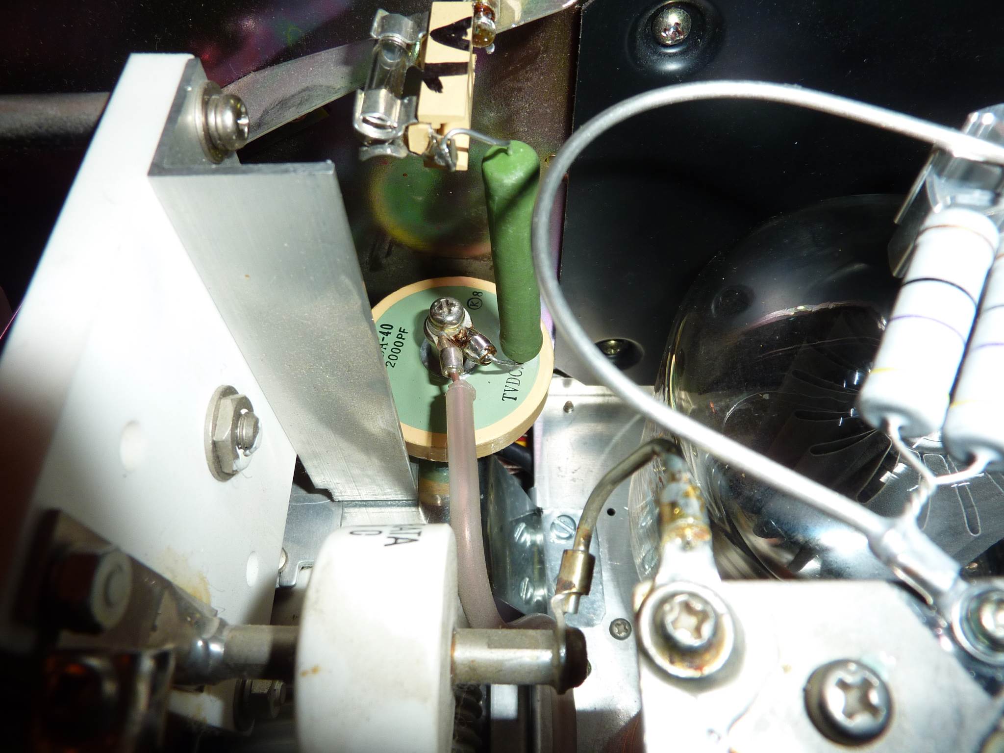
The 3-500Z tube has 3 grid connections on the socket. In the stock amplifier, these 3 inputs are DC grounded with an RFC and AC decoupled with 220 pF capacitors. Many users reported instability problems and one reason is this grid wiring.
The modification consists in putting these 3 grid connections directly to ground. There are several ways to do that... I did it by cutting small pieces of brass shim, one side solderd on the socket pins and the other side grounded at the mechanical fixing screws.
Another potential source of instability is the wrong ground return of the varaible capacitor VC1. The rotor is grounded via an aluminium square to the chassis, but this part of the chassis has no direct connection to the socket chassis, which makes a long DC loop ! I added a large aluminium strap between both chassis. I used the 2 existing screws on the VC1 side and drilled 2 new one in the grid chassis.
The last modification consists in replacing the original parasitic suppressor on tha anodes with loops and non inductive damping resistors. Dimensions can be found on different sites.
 |
 |
 |
| Grid grounding | VC1 ground return | Parasitic suppressors |
After all these modifications, i didn't notice any instability under any conditions.
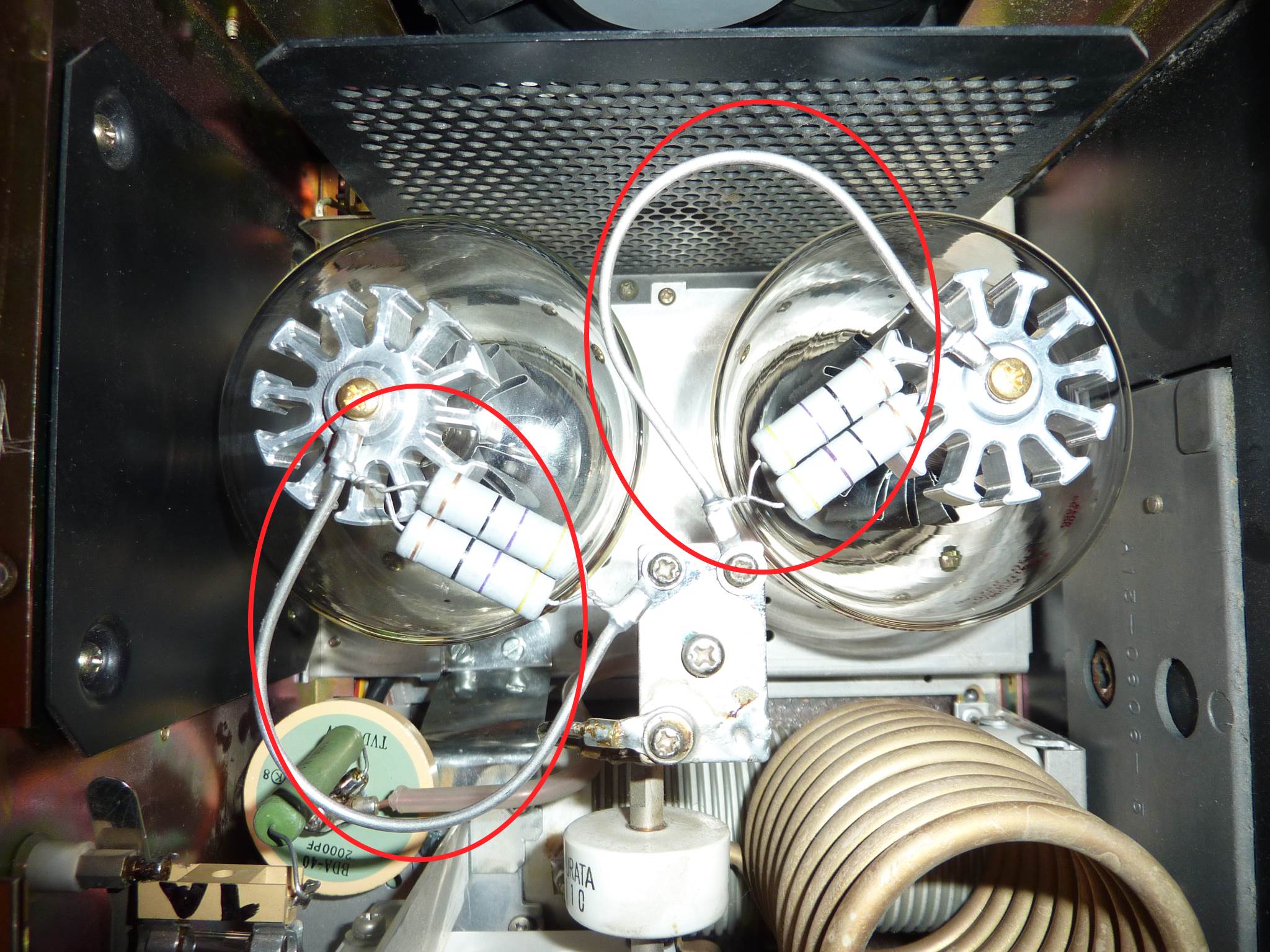
Symetrical cathodes feeding
In the stock amplifier, the filaments are wired in such a way that the cathodes are feeded on 2 differents pins. One tube is driven on pin 1 and the other one on pin 5.
The modification of the wiring allows a feeding on the same pins. As recommanded, i unsoldered the wire between both sockets and rewired it as shown. I had to lenghten one wire passing through the RF bead.
A picture is better then thousand words !
Conclusion
Once all these mods have been made, i powered the amplifier and everything went fine.
I first did heat the tubes with no HV power on them ( parasitic suppressor removed) for a few hours. Then in CW position, i mistuned the amplifier and injected a few Watts until i reached 200 mA plate current and waited the tubes to get red. I let them cool down and made this cycle a few times in order to reactivate the new tubes.
After that, i tuned the amplifier and increased the power until i got 100W input. I didn't notice any unstability under any condition. In CW position, with 100W input i measured 1000-1100W depending of band and 1400-1500W in SSB !