")
")
 Here is a description of an audio frequency tone decoder build around a PIC 12F683.
For a cost not much higher than a basic NE567, you will have :
- A more efficient decoder
- Far better stabiliy
- A settable threshold with hystereis
- Possibility to tune from 100 to 2148 Hz or use a fixed frequency
- No exotic or particular component
This article is my own feedback for a description found on this page.
A description on my own board for a fixed 1750Hz decoder used in my repeaters follows.
To build this decoder, you will need a PIC 12F683 programmer, the free MPASM assembler software if you want to modify the source for a fixed frequency decoder.
The original diagram :
The circuit description can be found here on the original page. I will not come back on this here.
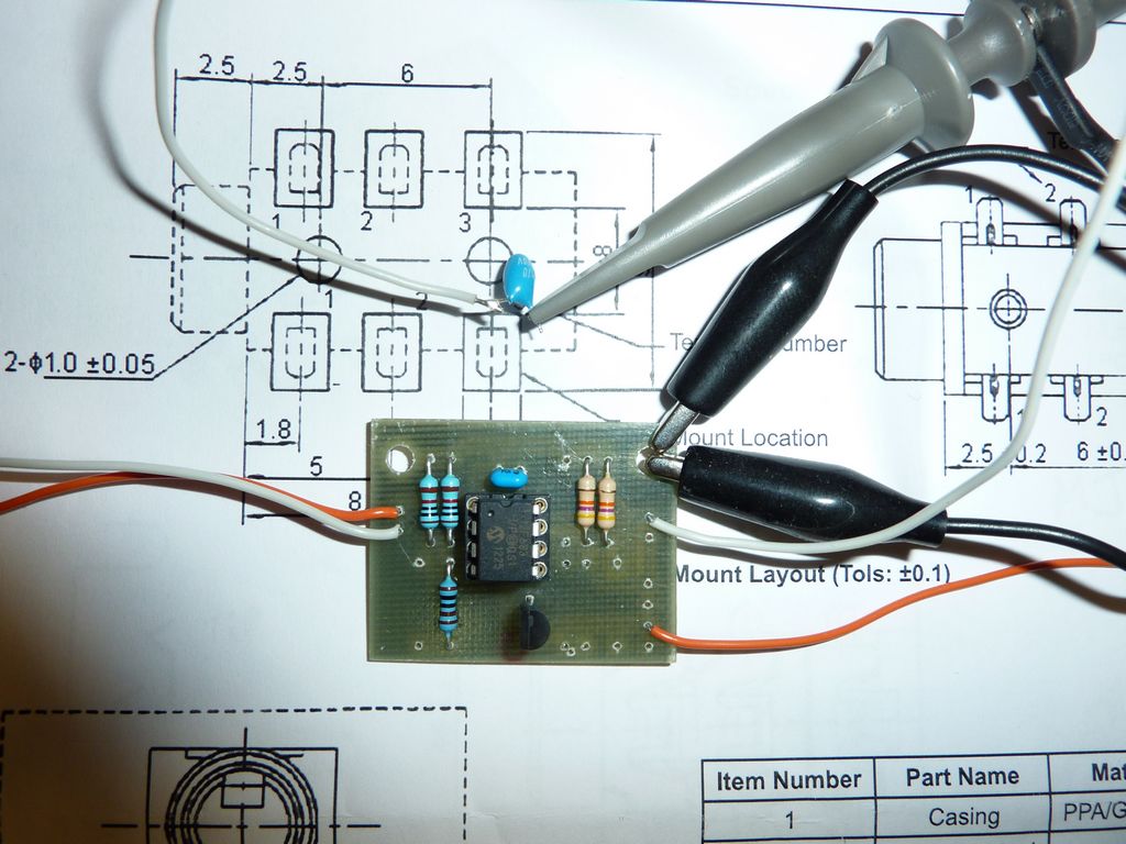
Buillding :
The following lines are describing what i did to replace the original 1750 Hz decoder built around the NE567 on a repeater controler board.
Despite all cares i took, (1% components, high quality capacitor) this decoder was unstable and had temperature drift problems. The following board is an addon board to solve this problem.
 The board is highly universal and can be used in other situations and projects.
To allow easier tuning (frequency and threshold), certain resistors have been split in 2 separate components. Different combinaisons are then possible to achieve the target value.
A transistor has been added to invert the output voltage that goes originaly high when the correct tone has been detected. Two outputs are now provided, one active high and one active low. This transistor can also drive another board or a small relay. Depending of your needs, you can ommit this transistor and resistor R7.
The software does not allow to decode the exact frequency of 1750Hz, but 1748 or 1752He, which is of no effect in practice.
The diagram and board have been made with the KICAD software. The following files are available :
- Decoder diagram.
- Printed board.
You also need to program a PIC 12F683 with the following code :
- Original HEX file for decoder
- Original assembler file for decoder for those who would like to modifiy the code...
To make things even easier, a special version has been made to decode ONLY the 1750 HZ frequency. Doing this, you can ommit R3/R4 and the resistor on pin4.
Below is the modified assembler code for this special version, as well as the HEX file to be programmed into the PIC. The code is commented, so you can easily modify the target frequency by changing the sin and cosin values found in the tables at the bottom of the code.
- HEX file for 1750Hz decoder
- ASM file for 1750Hz decoder
Natively, the software can only detect frequencies above 100Hz, so only a few of the TCS tones.
Please read the original article about the cares to be taken for low frequency decoding. (low pass filer, aliases)
For a central frequency of 1750Hz, i've measured a bandpass of 2%. The bandpass is not exactly centered on the target frequency. I've tested 3 PICs, and none of them had the good center frequency, one could even not detect the 1750Hz ! This is probably due to the internal oscillator precision.
You can adjust this in changing the voltage on pin 6, but this makes the thing not very reproductible.
An external crystal version will be studied...
21 feb. 2013 update :
Having build several boards, i noticed that the bandpass is not perfectly centered on the predicted frequency. (see above)
I supsected the internal oscillator precision and also a software approximation.
After some brainstorming and mails with the author, i finaly modified the software for the use with an external 8 MHz crystal just to eliminate the first possible cause. Despite the precision of the crystal, the problem was still there, but i had now all PICs on the same "wrong" frequency. This proved that the software had a small problem.
The author found out that this problem was coming from the few maths solved by this simple PIC. He had to use some tricks to make it work and that brings some approximations.
The target frequency has to be shifted a bit from 1750 to 1760 Hz, and everything works just fine !
The following software is for an external crystal reference and is centered on 1750Hz. The pins had to be re-arranged to be able to use pin 2+3 for the crystal.
The KICAD and PIC files for this better version :
- ASM file for an external 8MHz crystal and 1750 Hz detector.
- HEX file for an external 8MHz crystal and 1750 Hz detector
- KICAD diagram.
- KICAD PCB
Conclusion :
I have been amazed by the results of this little project. The author has made a wonderful piece of software and has squeezed all the code in such little room. It decodes perfectly and all my repeaters have now a troublefree decoding !
I hope this article will be of any interest for you.