")
")
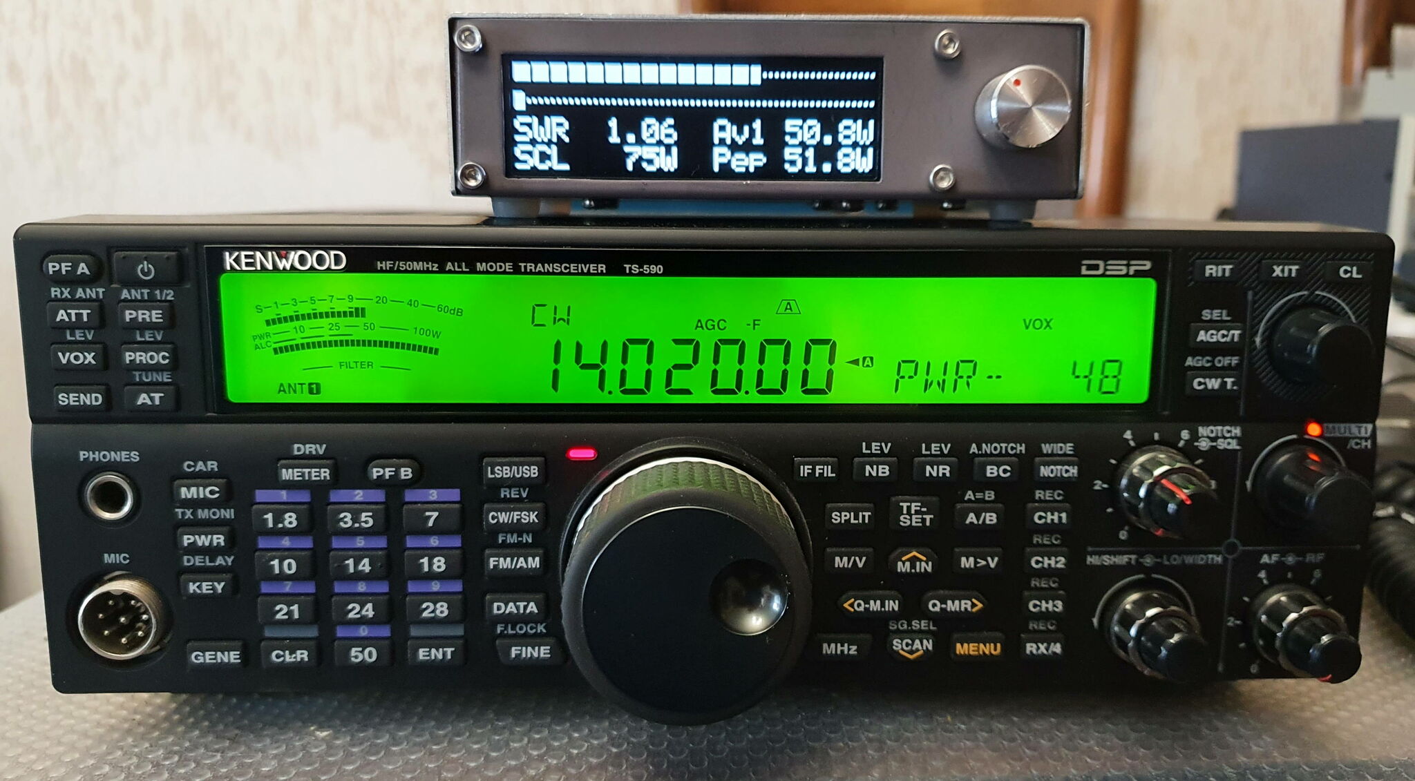 |
Wishing to replace my good old trusty BIRD 43 Watt-meter, I prospected a little on the Internet and found the description of an open source project for a Watt-meter which corresponded perfectly to my needs. This is a fork of the version made by TF3LJ, and developed by PD0LEW. A new hardware version was subsequently developed by WA2T. I chose the version with an OLED display, but there are versions with touch-sensitive TFT displays. |
| The main characteristics are: - 1-50 MHz range - measurement from a few mW to several kW - instantaneous, PEP, direct and reflected power measurement - measurement in W and dBm - fast digital display and 2 bargraphs using an OLED display. - automatic caliber change - configurable audible SWR alarm - coupler directivity > 30 dB up to 30 MHz and 20 dB at 50 MHz - etc. |
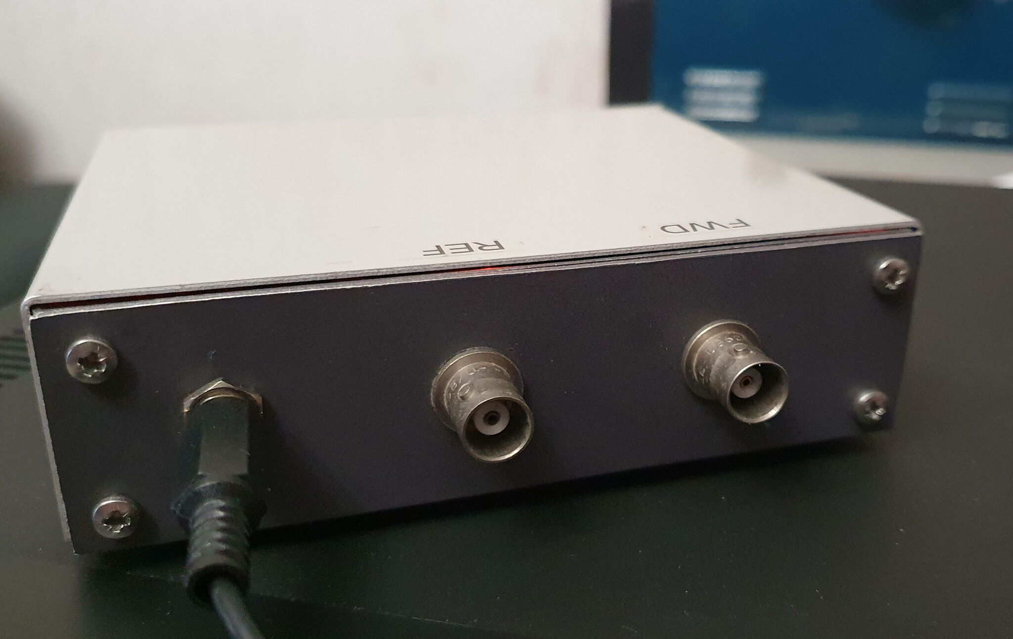
The assembly consists of a coupler installed in a shielded metal box and the Watt-meter with the digital display in another box.
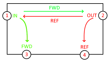
The connections between the 2 are made using 2 coaxial cables connecting the FWD and REF ports.
Coupler
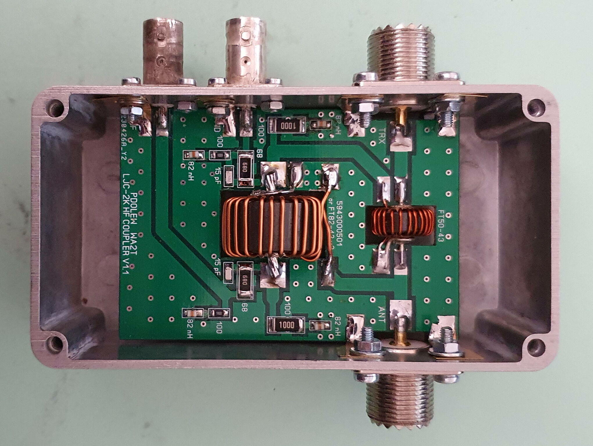
The coupler is made using a printed circuit and a HAMMOND 1590BS box.
It integrates a Sontheimer - Frederik type coupler followed by attenuators in order to make the levels compatible with the input levels of the CPU board.
The directivity is very good, the slightest mismatch is detectable. The use of SO239 sockets already introduces a measurable mismatch !
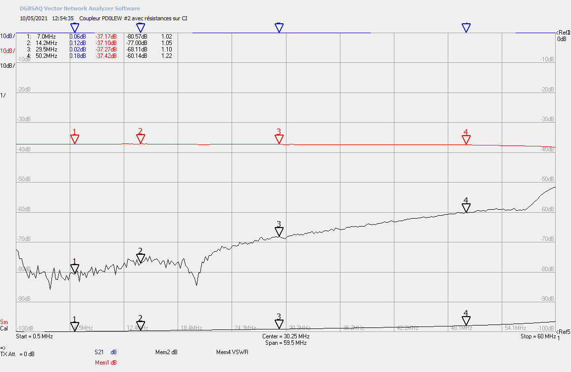
To test the effectiveness of the directivity, it is therefore necessary to solder a non-inductive resistor of 50 Ohm (for me 2 x 100 Ohm 1% CMS, in parallel) directly on the printed circuit at the output of the coupler. I thus measured between 30 to 40 dB up to 30 MHz, which is excellent and more than enough for our amateur needs!
Once put in a box with the SO239 connectors, we already measure a mismatch. Same as soon as you connect a piece of coaxial cable.
The transformation ratio of the 2 transformers is 24:1, so it provides a decoupling of 27.6 dB. Two attenuators are providing an additional loss of 9.63 dB on each port. The total attenuation is therefore 37.23 dB, which is confirmed by the VNA measurements.
In order to improve the frequency linearity of the coupler, an 82 nH inductor and a 15 pF capacitor have been added. I found that the linearity was better WITHOUT these components!
 |
 |
 |
Amplifiers and CPU
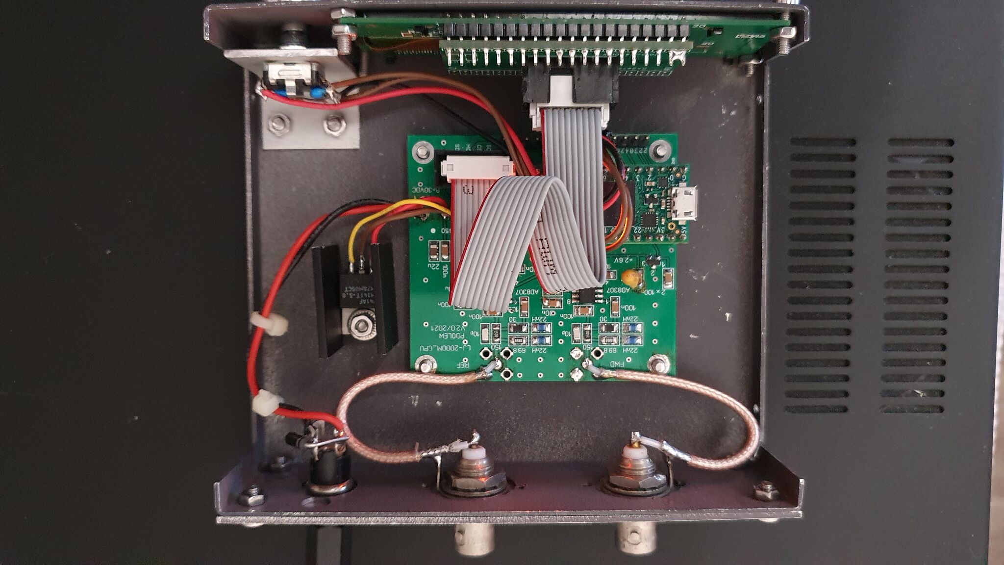
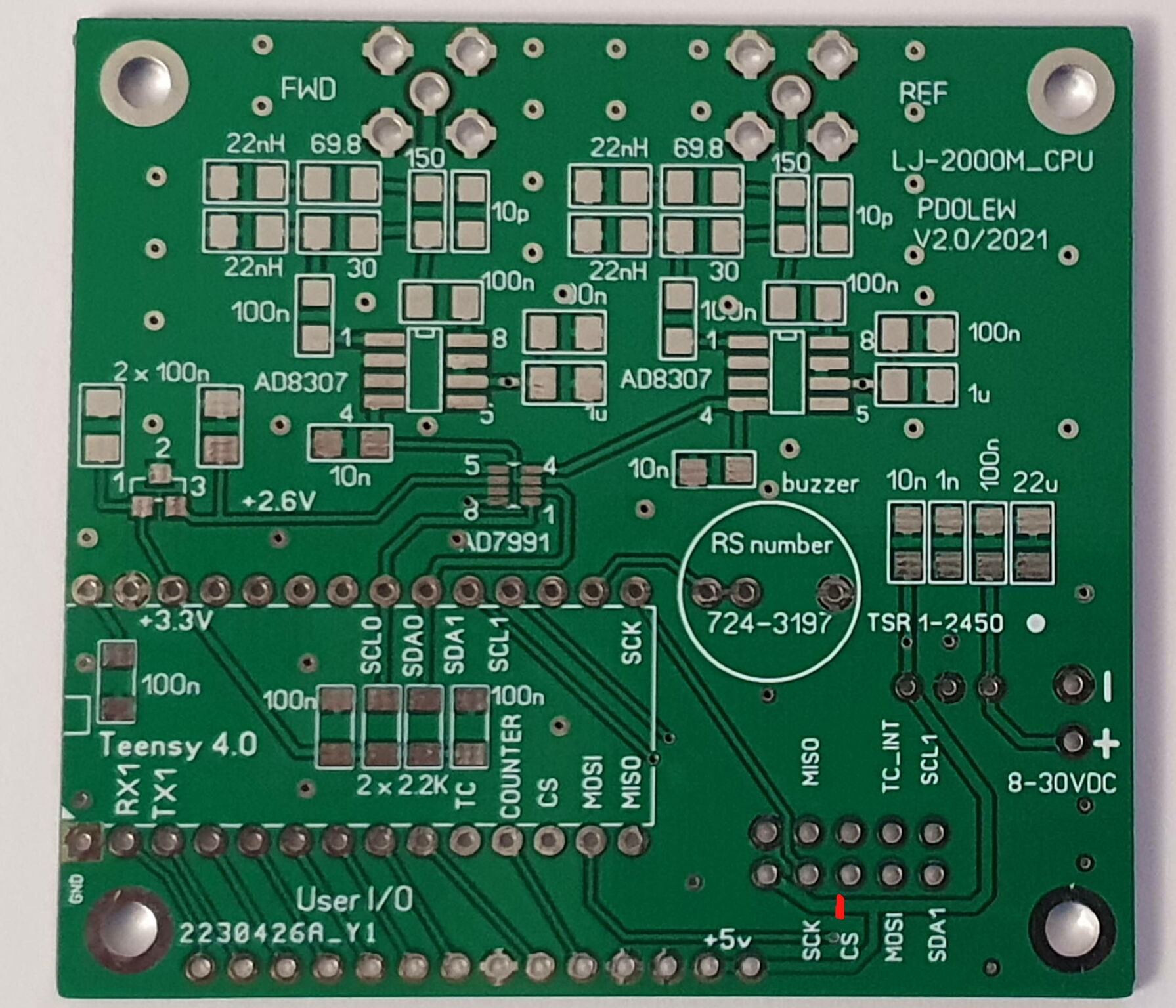
The CPU board mainly comprises a Teensy 4 microcontroller, a TSR1 5 Volt switching voltage regulator, 2 AD8307 logarithmic amps, an AD7991 A/D converter and an ISL6002 reference voltage source.
The analog outputs of the 2 amplifiers are sent to an AD7991 2-input 12-bit A/D converter. The result of the conversion feeds an I2C bus which is connected to the Teensy 4 micro-controller chosen for its speed of execution.
The precision reference voltage (here 2.600 V) required by the converter is provided by an ISL6002 regulator.
An encoder with pushbutton is connected to the board to allow navgation through the menus.
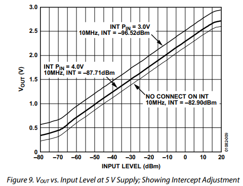
The AD8307 logarithmic amplifier has a very good dynamic (>70 dB) and good linearity if we stay between -60 dBm ad +10 dBm. In order to stay within this range, an additional attenuator of 15.76 dB is inserted at the input of each of the 2 ports FWD and REF amplificatin chains.
The coupling factor with the described coupler transformers with 24 turns is -27.6 dB.
The attenuator in the coupler has an attenuation of 9.63 dB. We need to reduce the power to be compatible with the AD8307.
The total attenuation is therefore 27.6 + 9.63 + 15.76 = 52.99 dB, say 53 dB.
From that we can calculate the power range that we can measure and still be within the linear range of the AD8307.
Maximum usable power within the limits of the AD8307 inputs.
(Max AD8307 input = + 10 dBm) + 53 dB = 63 dBm = 2 kW
Minimum readable power that can be measured in :
(Min AD8307 input = -60 dBm) + 53 dB = -7 dBm = 0.2 mW
But the usable minimum reading is not less than 10 mW.
That's more than fair !
The AD7991 is a 12 bits ADC that can be used with an external voltage reference, in our case it is a 2.600 V high precision regulator.
With 12 bit we can have a resolution of (2 power 12 ) 4096 steps.
So we have a step resolution of 2.600 V / 4096 = 0.635 mV.
When correctly used, the AD7991 as a slope of 25mV/dB at his output. So, the maximum resolution of the ADC is 0.635/25 = 0.0254 dB per step.
 |
Building the Wattmeter
For my part, I had the printed circuits made in China using the GERBER files available at the time. The CPU board is V2.0/2021 version and the coupler board V1.1
We will start by making the coupler.
It is ABSOLUTELY necessary to respect the winding direction of the transformers ! Take a good look at the photos and the explanations given here on the DJ0ABR site for an identical assembly, or in this document.
Small brass or copper jumpers allow good grounding of the board at the connectors.
The drilling of the case will be done so that the plate is halfway up the case. Any connectors can be used, the author uses SMA, I used BNC.
 |
 |
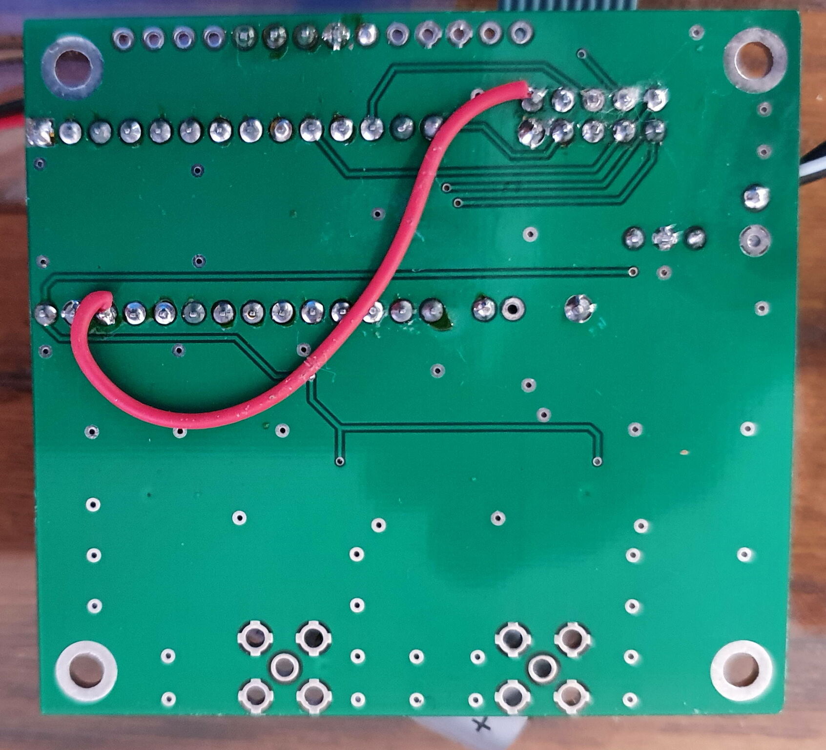
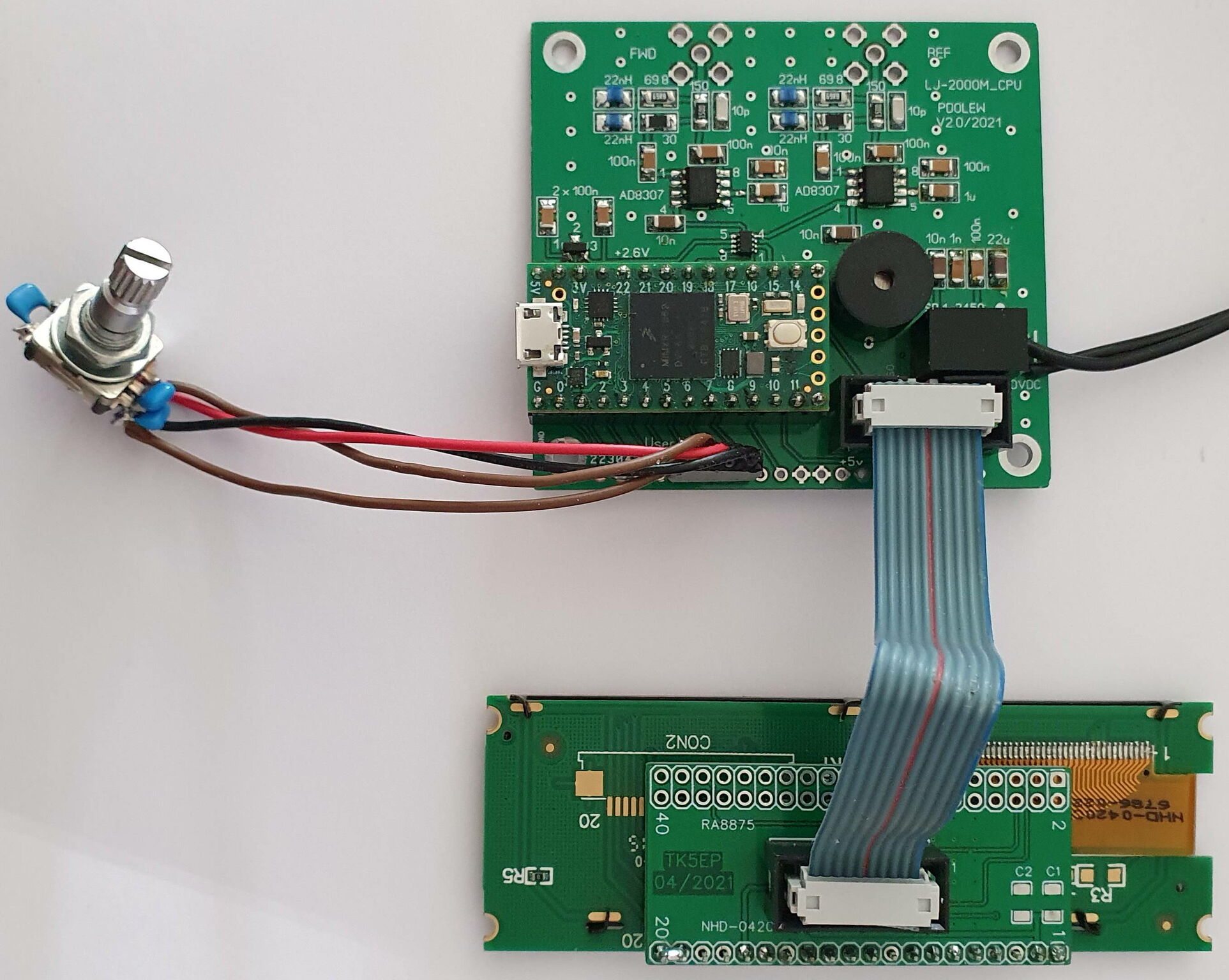
With the OLED display, there is a small modification to be made, namely that it is necessary to supply it with 3.3 V and not 5V as provided on the original printed board. The Teensy pins are not designed to work with a voltage of 5 V.
To be done BEFORE wiring the CPU board: You must therefore cut the track bringing the +5 V to connector J4 on pin 10 and solder a wire between this pin J4-10 and pin 24 (3 V) of the Teensy 4.
The rest of the board can then be wired. SMT soldering, specifically the integrated cituits, is quite tricky and requires good eyes and a calm hand. I made it with no problem, with a small soldering iron, desoldering braid and solder flux.
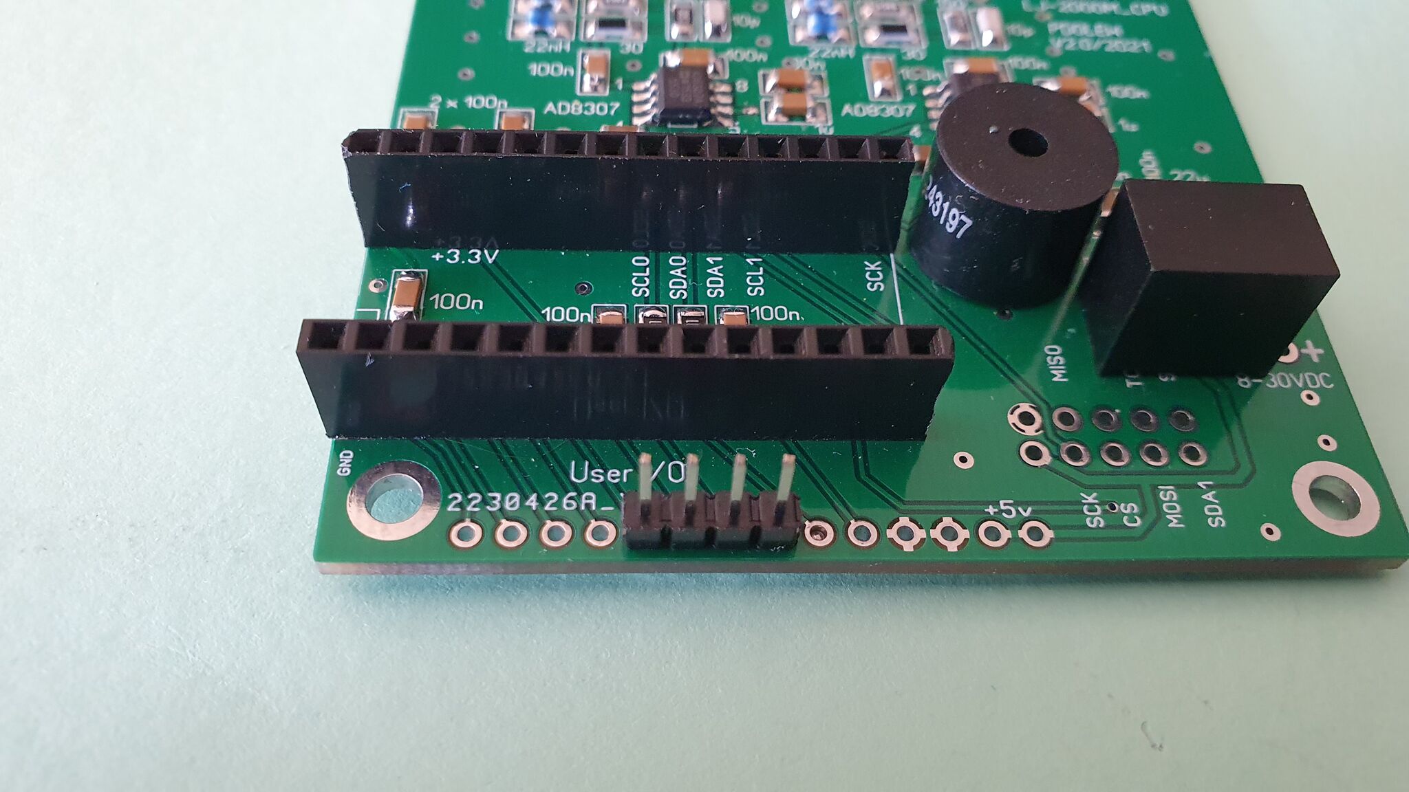
The Teensy will be mounted on pins in order to be removable if necessary.
The FWD and REF input connectors as provided on the printed circuit are SMA, I prefered to use BNC and a piece of coaxial cable. (see picture)
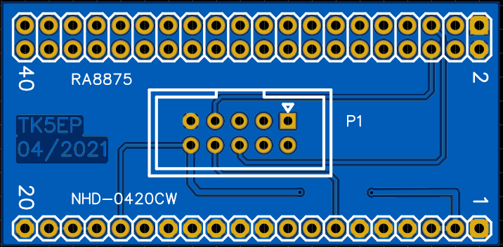
For the connection of the display, I made a printed circuit which allows the use of a ribbon cable of 10 conductors. This board can also be used with the RA8875 TFT display. I have a few board left, contact me if needed.
The encoder will be connected using 4 soldering pins as in the photo below.
 |
 |
 |
I also noticed that the TSR1 switching voltage regulator was generating quite a bit of noise on the 5 V line and which is reflected on the reference voltage of 2.6 V, thus marring the A/D converter with noise.
I replaced this regulator with an external 7805 attached to the case in order to dissipate the heat. The improvement is noticeable, the power display is much more stable. Adding some capacitors on the 5V and 2.6 V lines improves the problem without changing the regulator, but not as good as changing it.
Software
I was in constant contact with Johan PD0LEW who was very attentive and responsive. Together we corrected some bugs in the OLED version which is now little used, replaced instead by the TFT version.
For my part, I didn't need a large display with the touch screen.
The version I'm using is 2.1h. The latest version available on the download site is 2.1f.
There are 2 ways to program the Teensy 4, either with a file already compiled in .HEX format or by compiling the sources yourself using the Arduino IDE.
The first solution is the easiest if there is no need to modify the software. Setting up the IDE for Teensy requires several additions to the IDE and care must be taken to use the correct libraries provided by PD0LEW.
For programming the Teensy and the HEX file, you must use the Teensy Loader software available here.
Once the Teensy has been programmed, and the assembly checked from every angle to detect solder bridges, missing welds, the assembly can be powered up.
If the display shows something, the game is well underway ! ;-) Otherwise, everything will have to be checked again !
Calibrating
To calibrate the Watt-meter, it is necessary to have either another Watt-meter itself already calibrated or, as I did, a HF generator.
The software allows 2 types of calibration, in 1 or 2 points. The 1 point calibration is usually sufficient.
The output of the coupler will be loaded with a quality dummy load of 50 Ohm.
For a simplified calibration:
Enter SETUP mode by pressing the encoder and turning it until "Calibrate" is displayed and press the encoder button.
The encoder then makes it possible to choose "OneLevelCal" (by default). Adjust the value until displaying 47.0 dBm.
The last line should show "Poor signal quality"
With a transmitter precisely set to 50W (46.99 dBm), switch to transmission.
The poor quality message will disappear and be replaced by "Signal detected". Press the button to validate the measurement, "Value stored" should now be displayed.
Exit the menu by choosing "Exit"
Instead of the transmitter, a HF generator can be used. It will then have to be connected to the FWD input of the Watt-meter with a level corresponding to the level which would be present if a power of 50 W were applied to the coupler.
Remember that the coupler has a 37.23 dB attenuation !
For example : +46.99dBm - 37.23 dB = +9.76 dBm , but setting as 1st level to 47 dBm ! (as above)
Depending of your generator, any other level can of course be used, provided that the correct conversion into dBm is made. Use the highest generator output level possible !
Precise calibration:
If you want a calibration in order to have a more precise measurement over a wider power range and correct the small amplifier slope errors, you must use the 2 points calibration.
The procedure with 2 calibration points is identical as above, but using 2 different powers with a 30 dB difference and selecting "1st level" then "2nd level" choices. If the 1st point was set with 50 W, the 2nd will therefore be at 0.05 W.
If using a generator as described abovre, use the highest generator output level possible for the 1st level !
With a calibration on the FWD port only, it is assumed that the 2 amplification chains FWD and REF are identical, which is probably the case, but there may be slight differences.
To check this, swap both cables on the FWD and REF ports. If the measure is different, proceed for a REF port calibration like done for the FWD port (having done the FWD port calibration FIRST !)
The software detects that the REF port is being used and displays "Reverse detected" on the last line.
I hope all this helps ? Let me know with a short comment. :-)
Links
- Group Radio Stuff
- PD0LEWs home page