")
")
![]() For my SOTA activities, i recently bought a QRP transceiver QRP SW-3B, which is a three-band QRP CW only for 40/30/20 m.
For my SOTA activities, i recently bought a QRP transceiver QRP SW-3B, which is a three-band QRP CW only for 40/30/20 m.
So, i needed an antenna that would allow to use these 3 bands in SOTA portable activity.
Already having some experience with the EFHW antenna, i decided to build one for 40/30/20m.
The main advantages of this EFHW antenna are :
- easy to build
- multiband
- needs only one support, can be installed in line, inverted V, zigzag.
- fed at its extremity, can be directed connected to the transceriver, without any coaxial cable.
- the radiating part is at the center
All these advantages are welcome for portable operations and make this antenna a perfect candidate for SOTA
The radiating wire
A half wave wire can be fed at any point (end, off-center, center) without changing gain or efficiency... only impedance wil vary.
At each harmonic, the gain gets a bit higher and one lobe is added to the radiation pattern.
The EFHW cut on its fondamental band, 40m here, can be used on all harmonic bands : 40/20/10 m.
The resonating frequencies will probably not be exactly where you want them to be on the harmonic bands...Cut for 7.050 MHz, the harmonics will resonate a bit too high for the other CW portions... There are fortunately some solutions to lower the resonance on the harmonics.
To be able to use the antenna on other bands than harmonics, we need to have a system that can bring it to resonance on these bands.
This can be done in using links that are opened or closed, and traps.
The easiest method is to use links, but it needs to have access to the links and so to bring the antenna down for each band changing...
The theoretical length for the radiating wire can be calculated with my online Harmonic calculator
14.050 MHz = 10,14 m
10,120 MHz = 14,07 m
7.050 MHz = 20,20 m
The first section is fed at its end and resonates on the highest band (shortest wave length), the 20 m. Next comes a link and the complement to bring to length for the 30 m, so 14,07 m - 10,14 m = 3,93 m. Finally comes the rest for the 40m, so 20,20 m - 14,07 m = 6,13 m.
These lengths are purely theoretical and will need to be shortened due to the influences of the links or traps.
On my build, with a 0,6 mm plastic unsolated wire, and meaured at links end, i have 9,83 m, 13,68 m and 19,85 m.
Band switching with links
Any mechanical solution will do the job. I use small Epoxy boards and Faston connectors as can be seen on the picture below.
This method allows to build an antenna that can be used on any bands. I limited it to 3 bands, those of my transceiver.
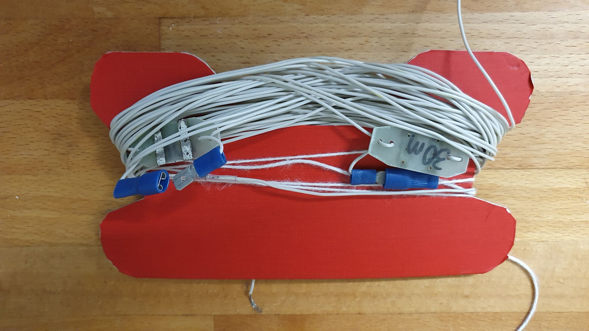 The wire is wrapped around a roller i've cut out of a piece of cardboard. It's very useful to avoid knots.
The complete antenna and roller weights only 120 g, but this can still be reduced by cutting out the unnecessary cardboard.
Band switching with traps
One trap per band is needed, and this can be really become a brain teaser ! It's cautious to use only 2 traps for 3/4 bands.
Any combination of inductance/capacitor can bring a trap to resonance for a given frequency, but the best results are obtained with the highest impedance. And this is achevied by using the highest inductance but still using a reasonable capacitor value.
Also, the trap resonance must be a bit lower than the lowest frequency to be used.
To keep size and weight as low as possible, ferrite toroids are used for winding the inductances.
The Web page toroids.info allows an easy calculation of all parameters for a given toroid reference. Very usefull site !
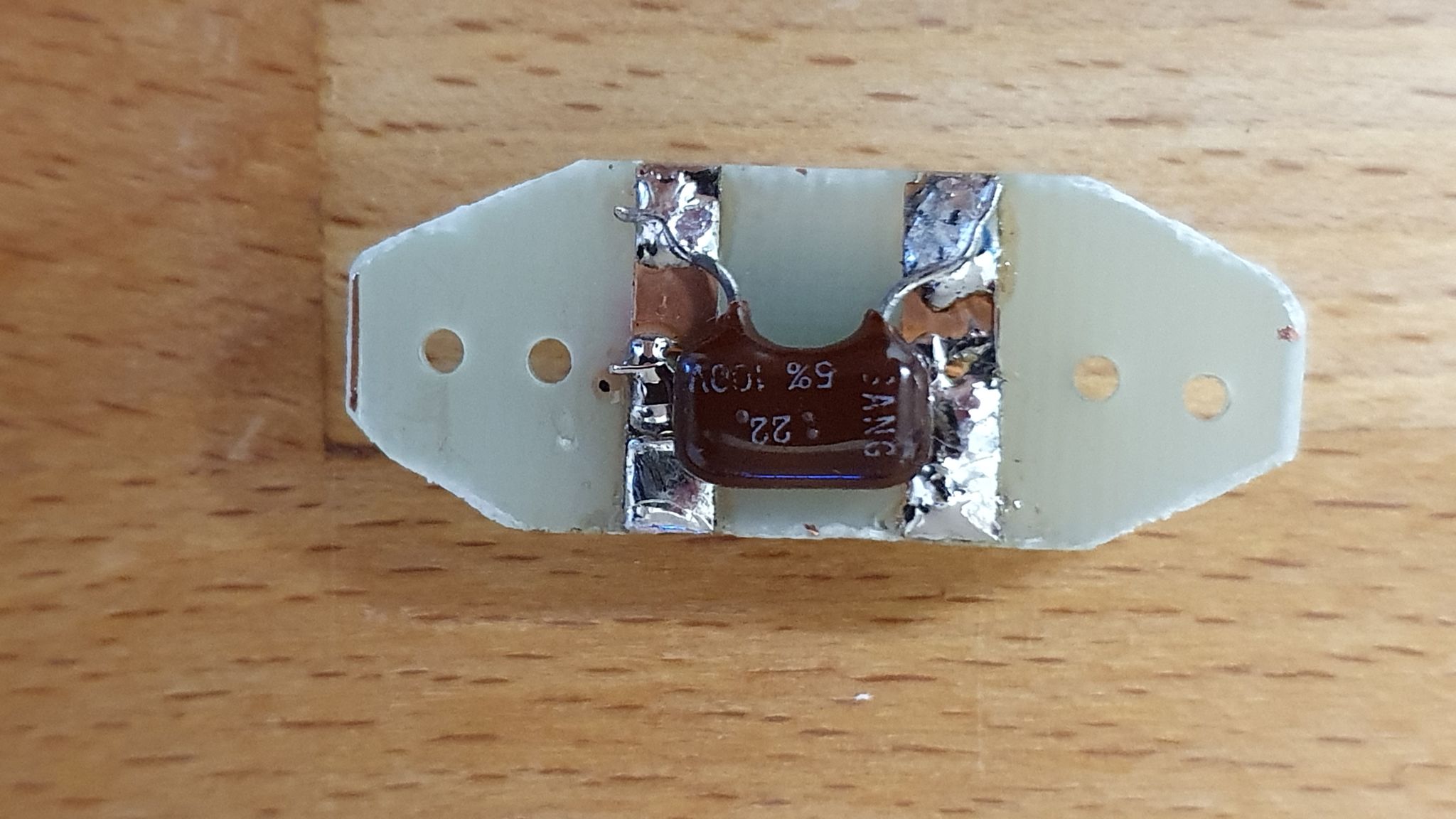
In my junk boxes, i had a few T50-2 and one T50-6, this later one is more adapted to the higher RF bands. I used a T50-2 for the 30m trap and the T50-6 for the 20m one.
I calculated the inductance for the Mica capacitor i had in my junk box, 33 pF for the 30m and 22 pF for the 20m.
Here an example for the 30m, at 10,0 MHz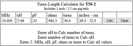
I've used small Epoxy PCB bands and have removed the copper with a cutter blade and left only 2 small bands of copper to solder the components and wires.
2 or 3 small holes are used to lock the antenna wires.
 |
 |
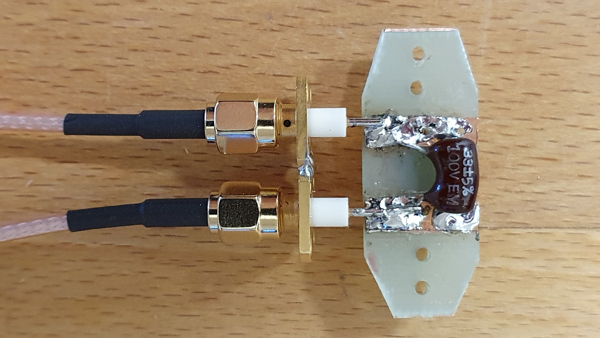
The tuning has been done with help of a NanoVNA and the following connector setup. I used the S21 LogMag and S21 group delay curves. Here the results.
 |
 |
 |
 |
Impedance adapter
A half-wave antenne fed at it's end has its voltage maximum at this end and so its maximum impedance.
This impedance varies from 2000 to 4000 Ohm depending of several factors (heigth over ground, shape, etc...)
It's therefore necessary to adapt this high impedance to our beloved transceiver output = 50 Ohm.
The are mainly 2 methods to achieve this, the transformer and the coupler. Each having advantages and drawbacks... (as always !)
The transformer is the easiest of both methods but is a compromise. It can't perfectly adapt the impedance for all frequencies.
I used a theoretical value of 2500 Ohm, which is a commonly adopted value for this EFHW.
The transformation ratio must then be 2500/50 = 50. In a transformer, the transformation ratio of the secondary/primary number of turns is the square root of the transformation ratio.
In this case, SQR 50 = 7,07. This value can of course only be an integer, so 7. So, the transformation ratio is 49 which is perfectly realistic with a final impedance of 2450 Ohm.
To build this transformer, we again use a ferrite toroid with a size and permeability allowing to handle the power and frequency range.
In my case 10 W max. and 7 to 30 MHz. A toroid with size reference 140 and material 43 fullfils this, so a toroid reference FT140-43.
We need to wind a transformer with a ratio of 7. 3 turns on the primary and 21 on the secondary will do the job. In order to have a better coupling between primary and secondary, the wires are twisted together. The higher bands SWR improvement is done by connecting a 100 to 150 pF capacitor across the primary.
The secondary is wound with a crossover at half number of turns, this crossover counts for a turn and brings the output in front of the input for easier mechanical setup.
 The result is a broadband transformer with a more than usable SWR on most of the ham bands.
Below a picture of the transformer with 2 resistors connected acting like a load for SWR control with a VNA.
More details about construction can be found on PA3HHO Web page [4] and in the Facebook group [3]
The coupler is the original EFHW adapter solution and is build to allow a tuning on any frequency with a bit more "fine tuning".
For a good working, the transformation ratio must be kept close to the 49, that we calculated above.
The parallel LC circuit is build in order to be tuned on the chosen operating frequencies.
 The principle.
The choice of components is therefore important ! Dimensions and power/voltage handling capacity must be taken into account.
In my case, running only 5W allows me to use small parts.
I owned a (measured) 11 pF - 153 pF miniature variable capacitor. This capacitor must be associated to a coil that must be dimensioned to allow a resonance on the highest frequency with the minimum stray capacity and on the lowest frequency with the highest available capacity.
Here also, the toroids.info Web page is of a great help to calculate all necessary informations. By choosing a T50-2 toroid which allows a 7 to 14 MHz working range, we calculate the ideal inductance L.
For example, considering a variation from 11 to 153 pF, if we choose (arbitrarily) a value of 140 pF (in order not to have a tuning at scale end) for a tuning at 7 MHz, we need an inductance of 3.69 uH.
Let's see what value C must have with this 3.69 uH inductance for a resonance at 14 MHz. The calculator gives us 35 pF, value which is covered by the variable capacitor still without been in abutment.. Perfect !
The calculator also gives us the number of turns and the needed wire length. The calculated turn number is 27.4 which is not realistic (must be an integer), so we have to choose 27 or 28..
If the tranformation ratio must be 49 as calculated, the turn ratio must be 7. So we choose 28 turns at secondary and 28/7= 4 turns on the primary.
A new calculation with this 28 turns value shows us that we are still OK within the capacitor variation. Just fine !
Our coupler will therefore have 28 turns on secondary and a variable capacitor of 11 to 153 pF to cover the 40 and 20 m bands.
If we want to cover more bands, we can add or remove some turns or fixed capacitors by using switches.
We will take care to keep a correct secondary/primary ratio. If we make both variable wih rotary swtiches, we will get a perfect tuning on any wanted band.
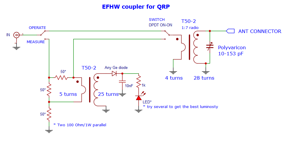
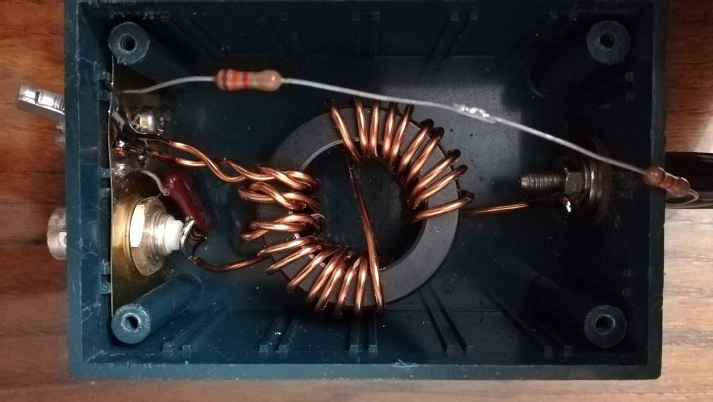
Below is a picture of my coupler. I've added a SWR indicator using a LED. The idea comes from N7VE and is very useful to get the perfect tuning !
At first, i was a bit sceptical, but now i'm convinced... The switch needs to be put in the temporary "measure" position during tuning and switched back to "operating" position after that.
But turning the variable capacitor while in receive and tuning for loudest signal already gives a VERY good result.
This shows us that the coupler is also a bandpass that can sometimes help rejecting other unwanted incoming signals. An advantage over the transformer solution.
On the other hand, the coupler solution needs more parts (also bigger for more power) and calculations.
![]()
![]()
Remarks
At the end of a EFHW some current must flow "somewhere". This can be done by earthening the coupler or tranformer or by adding some "counterpoise", without this there will be some shield current along the coaxial cable and everywhere you don't want it ..This can cause QRM, TVI, noise, etc...
Using this antenna only at low power and during portable activity, i didn't have to treat this problem. The coupler is connected directly to the transceiver and i never had problems. If using more power and a coaxial cable, you must consider the problem.
Various solutions are possible, from earthening, adding a 0.05 WL counterpoise, inserting a choke balun. You will find answers in the links below.
Have fun and see you on the air !
Annex
[1] Multiband End fad half wave" introduction and theory. N4SPP
[2] The endfed half wave antenna... why is it the most popular portable antenna ?
[3] Groupe Facebook End Fed Half Wave Antenna BE AWARE, it's close to as sect.. I've been censored there...
[4] Multiband HWEF by PA3HHO