")
")
 I used the Cushcraft A3 et A4s yagis and soon or later, problems are appearing..
Here are the results of my investigations and repairing technic, that can be applied to other models and trades as well.
What is described here applies to a A4s triband antenna, but the reasoning can be made for any multi-band yagi or vertical.
Symptoms :
The antenna is not resonating normaly, mostly on the 15m band. There is no real resonance and the SWR is high all over the band. The problem also appears on the 10 m band and more rarely on 20m.
Diagnostic :
Start adding a few meters of coaxial to check if there is no parasitic resonance. There must be no SWR difference, of very few.
Next replace the antenna by a 50 Ohm load. This will eliminate a coaxial feedline problem. SWR must of course be 1/1 !
Whatever failing band, start checking the dimensions using the original manual , as well as the continuity between elements and traps. The resistance of all junctions must be perfect, only a few center of Ohm.
If it's not the case, check for any aluminium oxyde which can isolate the elements and/or solder them together, sometimes in a irreversible manner ! There is no solution other then cutting and replacing the tubes..
The best is to be using aluminium grease as prevention ! Buying some grease is the best investment you can make !!
If the resistance between both ends of the traps is not VERY low (a few hundreed of Ohms), it's time to intervene of the traps.. To evaluate the low resistance, one can use my low resistance measuring technic .
Check also the traps orientation. When new, they have an arrow indicating how they should be mounted. But after some time outside in the sun, the printings are gone and a bad mounting is possible.
The 15 m traps can't be reversed, as they have a tapered extremity and have the thinest tubing at there end. For the 10m traps, the correct orientation can be determined by pressing on the black plastic caps. A small depression indicates the place where a screw is used to fix the external part of the trap to the inner element. This side MUST be looking toward the boom !
On 20m, all the elements and traps are in use, but no traps is resonating. A problem is generaly indicating a dimension or continuity problem.
On 15m, the problem is generaly a 15 m trap mistuning.
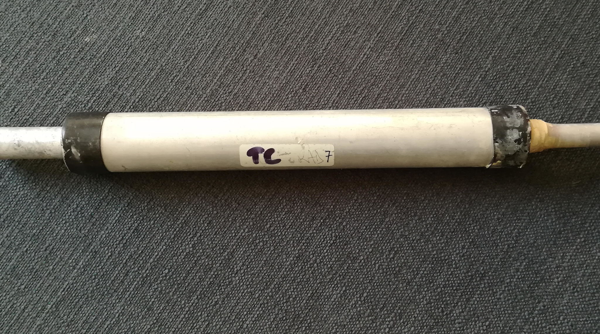
The 15m traps are at the end of the elements. On the A4s, there are 4 identical traps named TC on the radiator # 3 and reflector #1, and 2 traps TB on the director named #4.
On 10m, the traps is use are the closest to the boom. TD for the radiator and TE for the director. The 10m reflector is referenced #2 and does not have a trap.
If the 10m is failing, these traps have to be checked.
If everything that preceeds has been checked and corrected, a persisting problem will need the traps to be opened.
Controling the traps :
The "traditional" method described is with the use of a grip-dip which is coupled to the extremity of the trap. I've NEVER been able to use this method, my LDM815 grid-dip NEVER showed any absorption.
Owning a VNWA by DG8SAQ, i looked for a better method using a VNA.
I finally found an article written by IW2FND describing a way to do that. (link to his article)
I built 2 of his described "adapters" and started to succesfully test his method.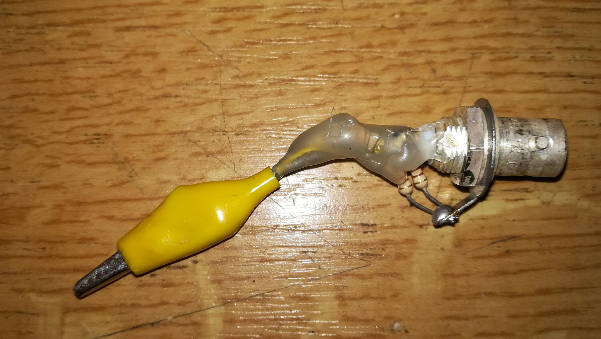 VNA adapter
I first set the software to show S21 PHASE and S21 Imaginaire in dB (Im dB)
For the 15m traps, i set the software to scan from 20 to 22 MHz with a sweep of 500 points at 12ms/point. (For 10m traps, sweep from 27-29 MHz.)
I than made a calibration in connecting both crocodiles clips and doing only a THRU and THRUMATCH calibration.
The trap to be tested is put on a cardboard box to minimize any effects by surrounding elements and the ouput of the VNA is connected to the tube which will be situated closest to the boom. The VNA input on the other side.
A scan will give you the trap resonance like something on this screen copy. (trap TC)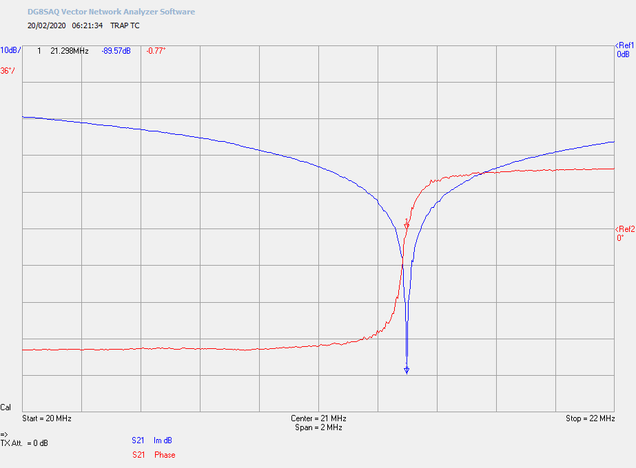
During my first measures, none of the TC traps showed a similar result (even close) and they were ALL resonating much lower than the 15m band (between 20,3 and 20,8 MHz), what probably showed a problem !
Being uncertain of my measuring method, i dismantled a trap to check if it had an internal problem.
Surprise... After dismantling the trap, (described later), the trap was full of grass certainly stored by small insects to make a nest. The grass was capturing humidity and was provoking a mistuning.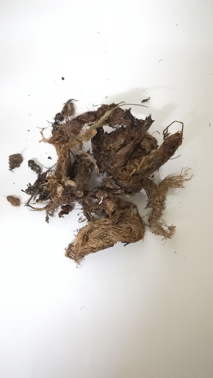
Once cleaned and reassembled, the trap showed a nice inband tuning what confirmed the problem and the effectiveness of the VNA method !
The six 15 m traps disassembled and cleaned, showed now close resonances.
The 2 TB were resonating on 21,450 MHz (+/-) and the four TC traps on 21,290 MHz (+/-). I counted 30 turns on TB and 31 on TC.
We can now put the good reference on each trap that have eventually been mixed.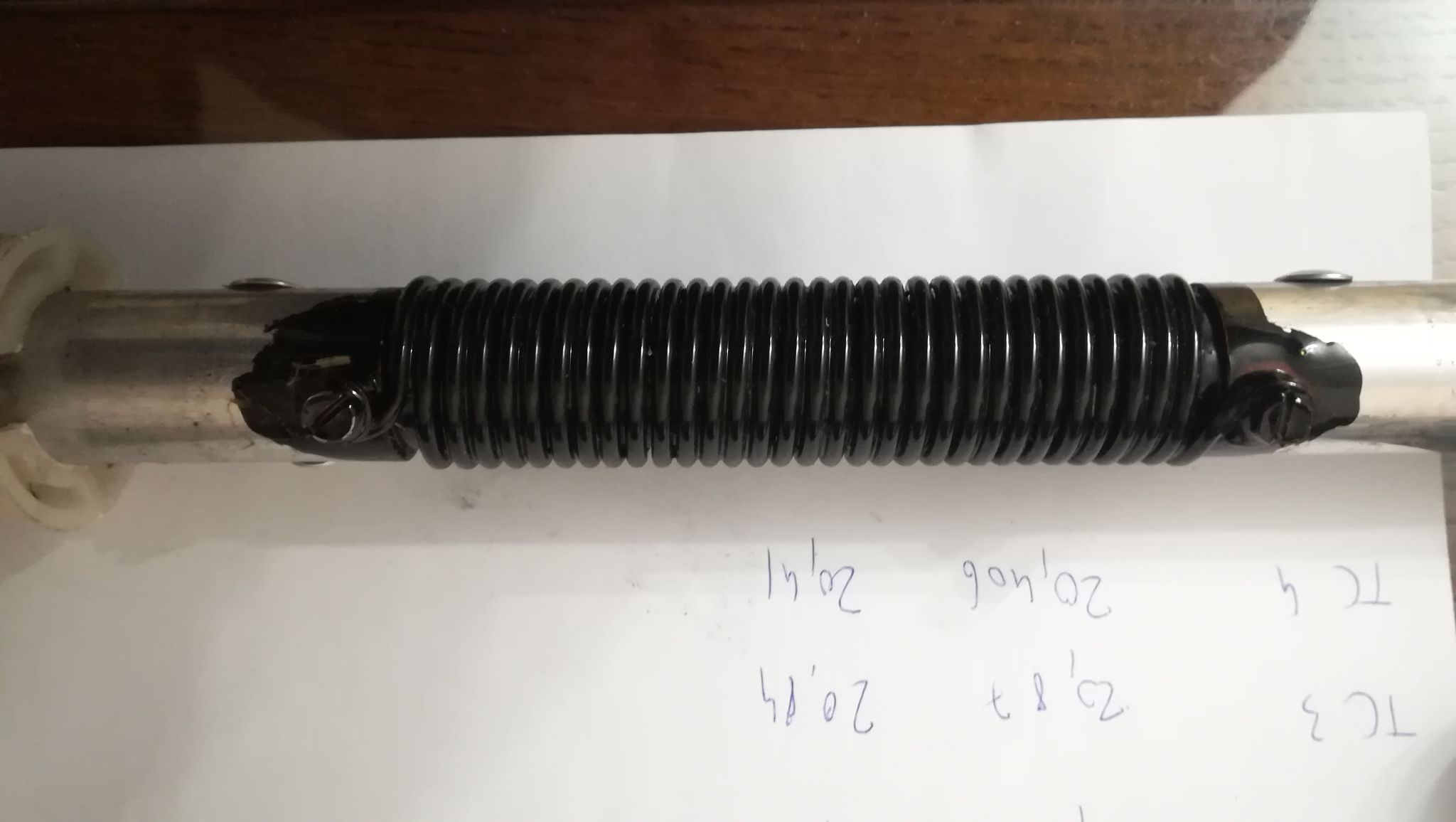
The TE traps are resonating on 28.650 MHz and the TD on 27.880 MHz
Trap disassembling
The 2 plastic covers have to be removed first. Proceed slowly and with care if you don't want to have leakages when putting them back.
On the "inside" extremity, a large screw is attaching the external part of the trap to the element. Remove this screw. On the other side, a circular insulator is slipped over the element and secured with 4 punches in the external tubing. These small depressions are inside a groove made in the insulator.
We need to remove these grooves before pushing the insulator out of the trap. I used a 2,8 mm drill. Drill slowly with the sharpest drill in order to produce the minimum of burr at the output. Otherwise, it will be even worse ! Make a test on a piece of thin aluminium.
Push on the internal element to slide it out of the trap. I used the handle of a hammer to do that. The weight of the hammer can also be used to give some slight chocs. There are 3 insulators to be slided ... Depending of your work on the grooves, it can be necessary to push rather hard ! Don't push on the insulators but on the aluminium tube.
Once removed, clean everything you can. Deburr the holes drilled to allow an easy reassembly of the trap.
Measure the resistance between the elements, it MUST be very low. If not, suspect a problem on the 2 screws attaching the coil to these elements. On all traps i checked, none had a problem here...
Using a very thin steel wool ( 000 ) clean all the parts, more particularly the one used for electrical contacts.
Reassembling
Slide the 3 insulators, one at each end and one in the middle of the trap. Carefully slide all the asembly inside the external tubing. Firmly tighten the screw.
I didn't make any punch to secure the insulator on the end of the tube. A bit of varnish can help but i didn't do anything...
Don't forget to put some aluminium grease on all connecting points.
Controling
Check the solidity of the reassembled trap and that nothing moves when shaking the trap.
Control the resistances as described above.
Check the resonance that should now be within the specifications given above.
If everything is OK, your antenna will be as new..
Good DXing !
Let me know if this helped...