")
")
 The orinality of this description is that the tone generation is made by the use of a DDS and not a sine wave generator made with transistors or a special circuit. It also does not use any special and expensive component but only junk box components, or at least cheap ones !
The main characteristics of this generator are :
- Two tone generator 800/ 1000 Hz or 400/2600 Hz (jumper selectable)
- Single tone generator of 1000 Hz
- Ajustable output level, max around 100 mV pp on 600 Ohm, or 35,4 mV eff. in single tone or 25,0 mV eff. in 2 tones
- Spectral purity between 0,3 and 150 kHz > 50dB !
- Distorsion <0,01% (in single tone) !
- Supplied by a 9V battery, consumption 7-8 mA that gives 50 working hours with an alcaline battery.
- Automatic PTT switching at power on.
This circuit has originaly been described by DH7AHN ,adapted and translated by myself for my usage. The original description can be found here
Principle of operation
The difference between the 2 frequencies generated in 800/1000 Hz mode is 200 Hz or a multiple of 200 Hz in the 400/2600 Hz mode. So, the signal is generated at a maximum rate of 5 ms. Thus the Eprom must follow the course of this curve at a max 5ms rate. To keep the circuit simple, the Eprom is adressed in binary mode and the software is written to match this. With a 14 bits divider, the clock frequency must be of 3,2768 MHz, which is a standard crystal frequency.
The xtal oscillator is a Collpits circuit built around transistor Q1. To keep the output at a sufficient level to drive the U1 divider, and to ensure an immediate starting of oscillation, the transistor type should not be changed. (but i also used BC337 with same results)) The clock signal is sent directly to the divider U1 input. The use of a standard CMOS component for which the upper operating frequency limit is 2 MHz is however not a problem. Using a "High speed CMOS" can generate parasitic spikes of about 10mV and has been avoided.
The divider outputs are driving the Eprom address inputs. The 3 Eprom outputs D0 to D2 are summed to give the digital output signal. The D/A conversion is done by 3 metal 1% resistors, which is enough in our case. The last spures of DDS switching are attenuated by 35 DB by the RC output filter. The output level is set by the multiturn ajustable resistor and the signal is sent to the microphone plug.
R12 and Q3 are used to key the PTT line as soon as the generator is switched on. If this solution shoud not be appropriate, this components can be ommitted and the transmitter should be keyed externaly.
A particularity of the circuit is the power supply switching. On this circuit, the negative pole of the battery is switched. DO NOT put the negative pole of the battery directly to ground, or the generator would operate permanently !
The reason of this particularity is to save the use of a double circuit three pole switch which is rather rare and expensive. The second switch is thus made by the Q2 transistor which is saturated in the single tone position. Q2 collector is used to switch the Eprom pin.
The jumper on pin 2 and 23 is used to switch between the 800/1000 Hz or 400/2600 Hz tones, this later values are recommanded in the Kenwood technical manuals. ATTENTION, the jumper must always be present in one of this position !
Diagram
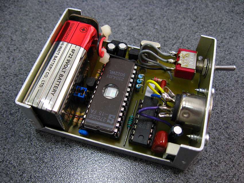
Construction
The circuit is built in a small aluminium case that can easily be found at most component dealers. It is a TEKO model 2/A.1 with dimensions of 72x57,5x28 mm. The printed board is 52x52 mm large and hosts all the components. A 9V battery supplies the circuit for many hours. The central position of the power switch cuts the supply, one position is for the 2 tone generator and the other one for the single 1000 Hz tone.
The battery is connected to the + and - pads of the printed board. DO NOT connect the minus of the battery to ground !
The diagram and printed board have been drawn with the free software suite ExpressPcb available here : http://www.expresspcb.com
You can download diagram file and the printed board file.
The software that must be loaded in the Eprom has been written by DH7AHN and can be downloaded here : 2tonprom.bin. The software was written to fit into a 27C64 or 27C128. I also used a 27C256, but you must put pin 27 to ground instead of +5V. You can do that by modifying the board or simply lift this pin form the board or socket and connect it to ground with a small wire.
Component layout
Operation
The generator is connected to the microphone plug of the SSB transmitter. Switch on the generator in the 2 tone position and adjust the generator output level at a sufficient level. A too high level can satured the microphone input of the TX and produce bad results.
The antenna signal is, after been attenuated or picked up by a coupler directed to the measuring circuit. If your oscilloscope has a maximum bandpass that covers the signal to check, you can use it directly.
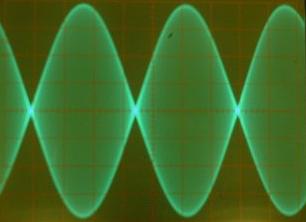
The signal envelope seen on the oscilloscope must have the following shape like in figure 9A.
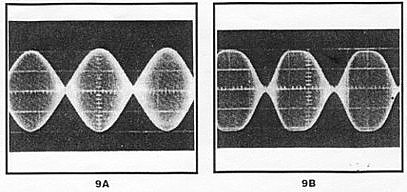
The crossing on the zero line must be very sharp and precise, the shape of the envelope must be clean and regular as in picture 9A. There are several defaults that can be detected with the help of this generator and method :
Overmodulation :
- the top of the curves are flat or distorted (figure 9B)
Bad carrier suppression or bad idle current :
- the crossings of the curves at zero are not sharp.
Lack of linearity.
- both symptoms and distorted curves
If you have a spectrum analyser, you can also visualize the signal. The SSB spectrum is about 2,7 KHz.