This page has no pretention and is not a complete description of the vertical antenna, it only is intended to help you understand the most important things about this antenna and to how make it work !
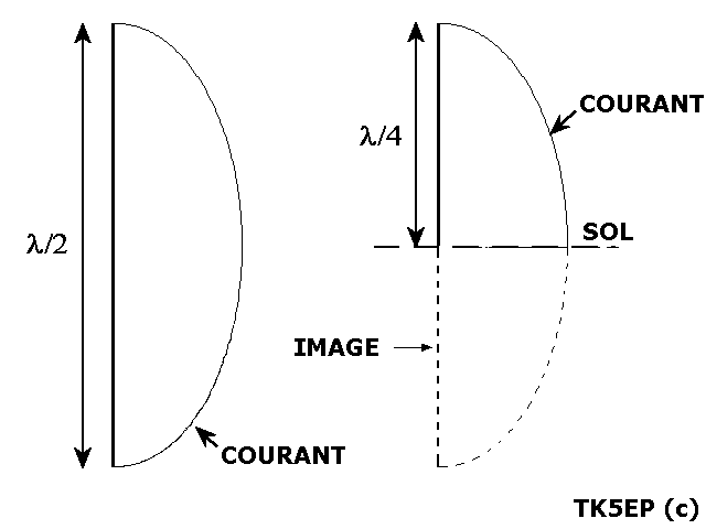 The simplest of all antennas is the vertical, also called the Marconi antenna. It has a quarter wave electrical length and has its base connected to earth.
This antenna vibrates with a intensity node (minimum) at his top, so at a voltage antinode (maximum).
Simple in its operation, it is by cons not the easiest to understand and handle.
Picture : The 1/2 wave antenna and it's equivalent mounted on ground. The missing 1/4 wave can be considered as its image in the ground.
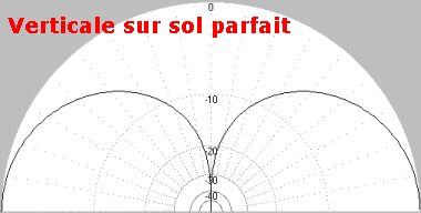 A PERFECT1/4 wave vertical would have at its resonating frequency the following characteristics :
- No horizontal radiation
- 5,1 dBi gain
- Maximum radiation at 0°
- Impedance of 36,5 Ohm
- No loss in the grounding system
PERFECT means no loss in the vertical radiating part, no loss in the grounding system (also called counterpoise, by analogy to mechanics)
In these conditions, with a 50 ohm coaxial feedline, you should accept a 1.4 SWR or add a matching system with a quarter wave line ot a LC circuit.
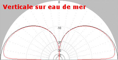 Unfortunately, perfection does not exist...
Consider the same antenna over the best earth that can be found : salt water (i know it's stupid)
The diagram already shows a visible difference :
- Maximum radiating angle : 10°.
- Gain loss : 4,45 dBi
- Impedance 36 Ohm.
This difference is due to a worse soil conductivity.
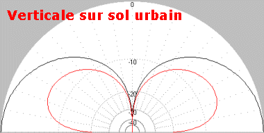 The same antenna, but this time over a bad soil (city lot). I don't wish that to anybody !
The diagram shows :
- Maximum radiating angle at 28°.
- Important loss : -1,01 dBi
- Impedance 36 Ohm.
We see that the soil nature is very important for this antenna !
![]() The efficiency of a vertical depends not only of the soil nature, but also other factors. Considering losses, the efficiency can be resumed by the formula :
The efficiency of a vertical depends not only of the soil nature, but also other factors. Considering losses, the efficiency can be resumed by the formula :
- Losses in the loads (coils, traps, etc...)
- Losses in the ground
In ground losses, we have to consider TWO TYPES of loss :
1) The ground at immediate antenna vicinity in which the current return will be done.
The power applied to the antenna has still not been radiated and the losses are dissipated in the ground and are reducing the radiatiing efficiency of the antenna.
2) The ground all around the antenna over a large number of wave length, typicaly > 2 for a quarter wave vertical.
It is in this part of the ground, called Fresnel zone, that the power radiated by the antenna will be reflected by the soil and will contribute to the reflection efficiency.
We see that for having an efficient vertical antenna, we can act on these 2 factors. If it is almost impossible to influence the second one (you can move to a remote island, water your garden), we can improve the first one in reducing the losses to their minimum.
With a poor ground and in order to have the best current return as possible, we can reduce the losses by placing a certain amount of radials.
These radials can be :
- laid on the ground.
- buried into the soil.
- raised over the groundl.
The first 2 methods are equivalent in terms of performances, except if you are burying the radials too deeply. Depth from a few cm to several tens of cm will not make a big difference.
Brown, Lewis and Epstein in their 1937 studies have shown that in order to obtain a perfect grounding system, 120 radials are needed !
Less radials means worse efficiency, more will not bring an improvement.... A reasonable minimum would be 16 radials of a 1/8 wave length.
Curiously, the number of radials also determines their length. The follwing table gives this relation :
| Nb radials |
4
|
12
|
16
|
24
|
48
|
96
|
120
|
| Length (Lambda) |
0,1
|
0,15
|
0,125
|
0,25
|
0,35
|
0,45
|
0.50
|
 In all cases were 120 radials are not possible, it is better to use surelevated radials.
Computer simulations and real-world tests have shown that 6 radials of 0.25 wavelength uniformely disposed around the vertical give the same result as 120 radials of 0.5 wavelength !! Only one radial is altough enough for a good current return, but the antenna will have a certain directivity and a horizontal component.
2 radials are correcting this.
CAUTION, using surelevated radials will lower the impedance down from 36 Ohm to close to 21 Ohm !!
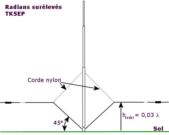
The radials must be tuned in order to reduce the radiation impedance. Their height over ground should be at least 0.03 wavelength, but this heigth depends of the soil quality. The poorer the ground, the higher the radials.
The best would be to elevate the base of the vertical in order to strain the radials at 90° (horizontaly). The higher the antenna, the better the gain.
When all this is not possible, the radials are placed at 45° from the base until they reach the right heigth and the rest will be strained horizontaly.
Some practical hints :
- I'm tuning the radials by pair (in opposite directions) in connecting them like a dipole and with the help of a noise bridge or a VNA placed at the base of the vertical. The important fact is tuning them to the right frequency, not for lowest SWR. Once tuned, they are reconnected at the antenna base.
- Use good insulators at the end of the radials, they have a maximum of voltage at this position. I've seen insulators of several cm taking fire under wet conditions !
- When using plastic insulated wire for the radials, you have to cut them shorter by 4 - 6% as the theoretical length.
- In case of lack of space, you can shorten the radials by placing coils (with some additional losses...) or bend their extremities.
- A vertical works well on a flat, clear and uniform ground.

