")
")
Some notes on how to use a SIM800 coreboard with an Arduino.
I bought the following cheap SIM800L board and have had some problems to make it work.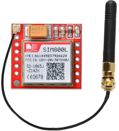
ATTENTION !
This board doesn't have any voltage regulator nor level adapters. Special cares have to be taken if you don't want to burn the module !
- The power voltage applied to the VCC pin has to be between 3,7 and 4,2 V. NOT less, not more
- The voltages used on TXD and RXD on the serial port must be between 2.5 and 2.8 V for HIGH level and 0 to 0.1 V for LOW level.
POWER SUPPLY
As mentioned above, the supply voltage must be in the 3.7 - 4.2 V range. Feeding it with the 5V of the Arduino will destroy it. With 3.3 V, it will not work at all !!
The board CAN consume as much as 2 A in burst mode. Some precautions has to be taken !
The supply must be able to feed up to 2 A without any voltage drop or there will be permanent reboot that can be unnoticed and lead to some headackes !
A good LiPO battery, a stable step-down supply or a regulated PSU will do the job. I used a DC-DC buck converter for my tests and later a LM317 regulator adjusted to 4 V.
Long and small wires can have enough voltage drop to make to supply voltage go under 3.7 V. Avoid this...
Adding a large electrolytic capacitor between VCC and GND pins can help reducing these drops, but you really should not need it with a good power source.
SERIAL PORT
The voltages on the serial port (TXD and RXD) MUST be within the given voltages. Using 5 V levels will certainly burn the module !!
If your arduino is a 3.3 V version, little has to be done to reduce the voltage. I used the following interface with success :
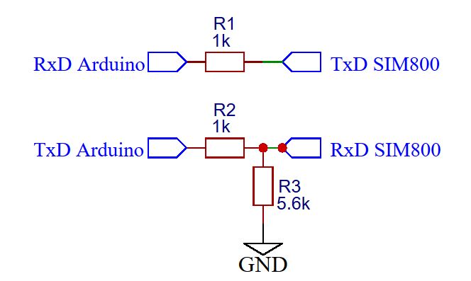
If your Arduino is running on 5 V, a little more work must be done.
The SIM800L hardware manual gives a 2 transistors level shifter diagram or you can use a logic level converter module like this one :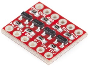
Each side of the interface has to be powered with the supply voltage of the module on which it is connected.
SIM CARD
The module uses a MICRO SIM socket. The right insertion direction of the SIM card is engraved on the socket (very small though !).
The right way is the SIM with the notch outside and metallic parts (contacts) against the board.
Don't insert by error a NANO SIM or you will have troubles to get it out of the socket and probably will destroy one or more socket contacts as i did !
Preliminary test :
Insert a valid SIM card that does not have a PIN code.
Connect a decent antenna.
Supply the module and look at the flashing LED.
It should flash at 1 s rate and after a few seconds, it should flash at a 3 s rate telling that it ias registered on your network.
If this does not happen, you have a problem :
- the module has not been flashed for your area and does not recognize your network provider
- your SIM card is PIN code protected or is not registered at your provider
- your power supply is unstable
- your antenna does not work or you're out of coverage.
Try to solve this problems first.
Wiring :
The TxD and RxD pins must be crossed between the Arduino and the SIM800. That means Arduino RXD is connected to TXD of SIM800 and Arduino TXD connected to RXD of SIM800.
Be careful with the grounds, especially if you use a regulator or stepdown module ! Missing a ground can lead to lethal voltages for the module !!
Connect an antenna to the module.
Testing the communication
Once you've passed the preliminary test, you can connect your module to the Arduino with the given instructions.
Download the following sketch and set the few parameters PIN_TX, PIN_RX, SERIAL_BAUD in the sketch, according to your needs. Compile and transfer it to your Arduino.
Run the sketch and see what happens.
After a while, you should see the module flashing at a 3 s rate and the information on screen will tell you if everything works as expected.
The software does :
1) send the AT command. The SIM800 should answer "OK".
2) send the ATI commande to get the module name and version
3) send the AT+CSQ command that gives the signal strength. You should have an answer like CSQ (10,0)
4) send the AT+CCID command that will check if the SIM in inserted and give you the SIM number.
5) send the AT+CREG? command to tell you if your module is registered on your providers network. +CREG: 0,0 means that the module is not registered.
6) send the AT+CPOWD=1 command to make a software POWER DOWN. The LED should be OFF.
If you have normal answers, you're saved and can create your own sketch.
If not, you must :
- check if the TX_PIN and RX_PIN settings in the sketch are respectively the TxD and RxD pins used in the Arduino.
- check the wiring between the Arduino and module ( RXD and TXD)
- if you have garbage on the screen, set the SERIAL_BAUD parameter to your terminal speed (default 57600 Bds)
Software
I don't use any library for my Arduino sketches and use the the AT commands.
I lost some hours while trying to use the CPIN command to enter the PIN code to unlock the SIM card. Until i finaly found out that you NEED to send the following commands to make it work :
AT+CPIN (the module should answer OK)
AT+CPIN=xxxx (xxx being the PIN code and the module should answer OK)
using the AT+CPIN=xxxx did not work ...
Notes :
SIM800L hardware manual
SIM800L AT command list
Best SIM800 related web page i've found, on lastminuteengineers.com