")
")
Description of a PCB, also called "shield" allowing to build a universal rotator interface based on the K3NG software. Only the AZIMUT function is supported.
This PCB has been thinked to be used either with a LCD display or an Ethernet shield to allow a remote usage via IP, and for a rotator using a variable resistor for the azimut value . (HAM IV or CD44 in my case)
 The board includes :
- a 5V/1A regulator
- a header to plug an Arduino UNO and an Ethernet shield
- a HE10 male connector for to LCD display with a ribbon cable
- a 5 pin DIN connector (+ ground shell) to connect the rotator control box
- 2 connectors for the "Clockwise" and "Counterclockwise" pushbuttons
- a multi-turn ajustable resistor VR2 for the azimut calibration
- an ajustable resistor VR1 for the LCD contrast
- 3 transistors for the CW, CCW, and BRAKE commands (open collector outputs)
I still have some naked pcb boards left. If interested, please feel to contact me.
The 5V/1A regulator is necessary in order to supply the Ethernet shield which requires a lot of power, too much to be fed by the UNO onboard regulator. It also provides a stable voltage reference for the azimut value. As a precaution, i removed the onboard power supply connector and fuse on the Arduino UNO, in order to remove the accidental risk of supplying the UNO. It also saves an unneeded back panel cutout.
The PCB includes 3 boards that have to be cut with a small hacksaw. At the end, there are 3 PCBs :
- 1 main which will support the Arduino UNO and all components.
- 2 small PCB for the LCD display (only one needed)
These last ones are unfortunately unusable as is, i made a mistake during the design.... :-(
Some modifications are needed... A few tracks to cut and wires to solder.. It also depends of your LCD board.
A cheap Arduino UNO is enough for both usage (LCD or REMOTE). It is however necessary to desactivate all unneeded settings in order to squeeze the software in the limited RAM.
Operation with a 2 lines LCD
In this mode, the board has to be completely wired and a 2 lines LCD display is needed.
The HE10 connector on the PCB is used to connect the LCD board through a 10 wire ribbon cable. I have used a 122 x 44 mm ABC016002 LCD display i bought on ebay.
Pin correlation for this LCD :
| LCD | HE10 | PCB | |
| 1 | LED K | 3 | GND |
| 2 | LED A | ||
| 3 | GND | ||
| 4 | +5V | 1 | +5V |
| 5 | Vo | 7 | Vo |
| 6 | RS | 9 | 8 |
| 7 | RW | 5 | GND |
| 8 | E | 10 | 9 |
| 13 | D4 | 8 | 10 |
| 14 | D5 | 6 | 11 |
| 15 | D6 | 4 | 12 |
| 16 | D7 | 2 | 13 |
The main PCB allows the soldering of a variable resistor to adjust the LCD contrast. It can be omitted if this resistor is soldered on the small display board. CAUTION, only one of these resistors has to be used !
K3NG software settings available here
It is necessary to modifiy the 3 parameter files like this :
rotator_features.h ( comment all the instructions with a // at line beginning )
#define FEATURE_YAESU_EMULATION
#define LANGUAGE_ENGLISH
#define FEATURE_4_BIT_LCD_DISPLAY
#define FEATURE_AZ_POSITION_POTENTIOMETER
#define OPTION_DISPLAY_HEADING
#define OPTION_DISPLAY_DIRECTION_STATUS
#define OPTION_SAVE_MEMORY_EXCLUDE_REMOTE_CMDS
#define DEFAULT_DEBUG_STATE 0
rotator_pins.h ( set all other values to 0 zero )
#define rotate_cw 6
#define rotate_ccw 7
#define brake_az 5
#define button_cw 4
#define button_ccw 3
#define rotator_analog_az A0
#define lcd_4_bit_rs_pin 8
#define lcd_4_bit_enable_pin 9
#define lcd_4_bit_d4_pin 10
#define lcd_4_bit_d5_pin 11
#define lcd_4_bit_d6_pin 12
#define lcd_4_bit_d7_pin 13
rotator_settings.h ( modify the following lines )
#define LCD_COLUMNS 16 (LCD 16 characters)
#define LCD_ROWS 2 (LCD 2 lines)
#define LCD_DIRECTION_ROW 1 (azimut display on line 1)
#define LCD_HEADING_ROW 2 ( heading on line 2)
Once the configuration files have ben modified and the software compiled and loaded in the Arduino, the display contrast and the rotator voltage have to be adjusted.
Mode detais can be found in my previous article.
Operation in REMOTE mode
In this mode, an Arduino UNO and an additionnal shield Ethernet are needed.
It is therefore not necessary to solder the HE10 connector, neither the components VR1, P2, P3, C1, C2. The LCD display can't be used simultaneously because several pins are used by the Ethernet shield.
The Ethernet shield is plugged on the main PCB and the UNO on top of it.
K3NG software settings are available here
It is necessary to modifiy the 3 parameter files like this :
rotator_features.h (comment all the instructions with a // at line beginning)
#define FEATURE_YAESU_EMULATION
#define LANGUAGE_ENGLISH
#define FEATURE_AZ_POSITION_POTENTIOMETER
#define FEATURE_ETHERNET
#define FEATURE_MASTER_WITH_ETHERNET_SLAVE
#define OPTION_SAVE_MEMORY_EXCLUDE_REMOTE_CMDS
#define DEFAULT_DEBUG_STATE 0
rotator_pins.h (set all other values to 0 zero )
#define rotate_cw 6
#define rotate_ccw 7
#define brake_az 5
#define rotator_analog_az A0
rotator_settings.h ( modify the following lines to your IP environment )
#define ETHERNET_IP_ADDRESS 192,168,0,10
#define ETHERNET_IP_GATEWAY 192,168,0,254
#define ETHERNET_IP_SUBNET_MASK 255,255,255,0
#define ETHERNET_TCP_PORT_0 23
CAUTION, before any connection to the rotator, the VR2 ajustable resistor has to be turned to ground side in order to limit the voltage on the analog input pin. A too high voltage on pin A0 pin of the Arduino can destroy it !
For this, measure the resistance value between test point TP3 and ground, and adjust VR2 to read 0 (zero) Ohm on an Ohmmeter.
Once the software loaded in the Arduino, VR2 has to be adjusted to calibrate the A/D (analog/digital) converter input.
For more details, read my previous article.
Construction
Using a smal hacksaw, cut the PCB in 3 parts following the lines on the PCB. The thinner the blade, the better !
If the REMOTE version is build, the 2 small LCD boards are not used.
Start to solder the power supply part of the main PCB : J1, C3, C5, C8, U1. A small heatsink under U1 is needed only for the REMOTE version.
Connect a 12V on J1 (+ on central pin, - to ground) and measure the voltage between TP2 and ground. You should find something very close to 5V. Note this value for the rest of the procedure. On TP1, you should have the same volatge as the 12 V power supply.
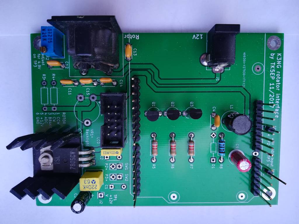
You can now solder the other components. CAUTION, if using a BC337 type, the 3 transistors Q1, Q2, Q3 have to be soldered reverse of the serigraphy. ( nobody is perfect ! )
You will need a header with rather long pins to plug the UNO or Ethernet board. Otherwise, they will touch the components. I've used 15 mm long pins.
When wiring in LCD or REMOTE mode, some components are not needed.
R3 + R4 are only needed when using a 2 wires rotator. They are not used with a classical 3 wire direction potentiometer.
D1, initialy intended to protect the Arduino input intoduces too much load and has a negative impact on the linearity and is not wired.
In REMOTE mode, do not solder VR2, C1,C2, P1, P2, P4, D1.
In LCD mode, do not solder D1. Heatsink under U1 is not needed. VR2 can be omitted if wired on the LCD board.
The small LCD board is plugged behind the LCD display board after having soldered some wiring pins on the display. On the below picture it has been soldered at right angle for test purposes and to show the modifications made on the board. In "real life" it is soldered so the PCB is parallel to the LCD board.
Depending of the display type, some tracks have to be cut and some wires added. Make your own wiring if necessary.
Picture below is for the mentionend display.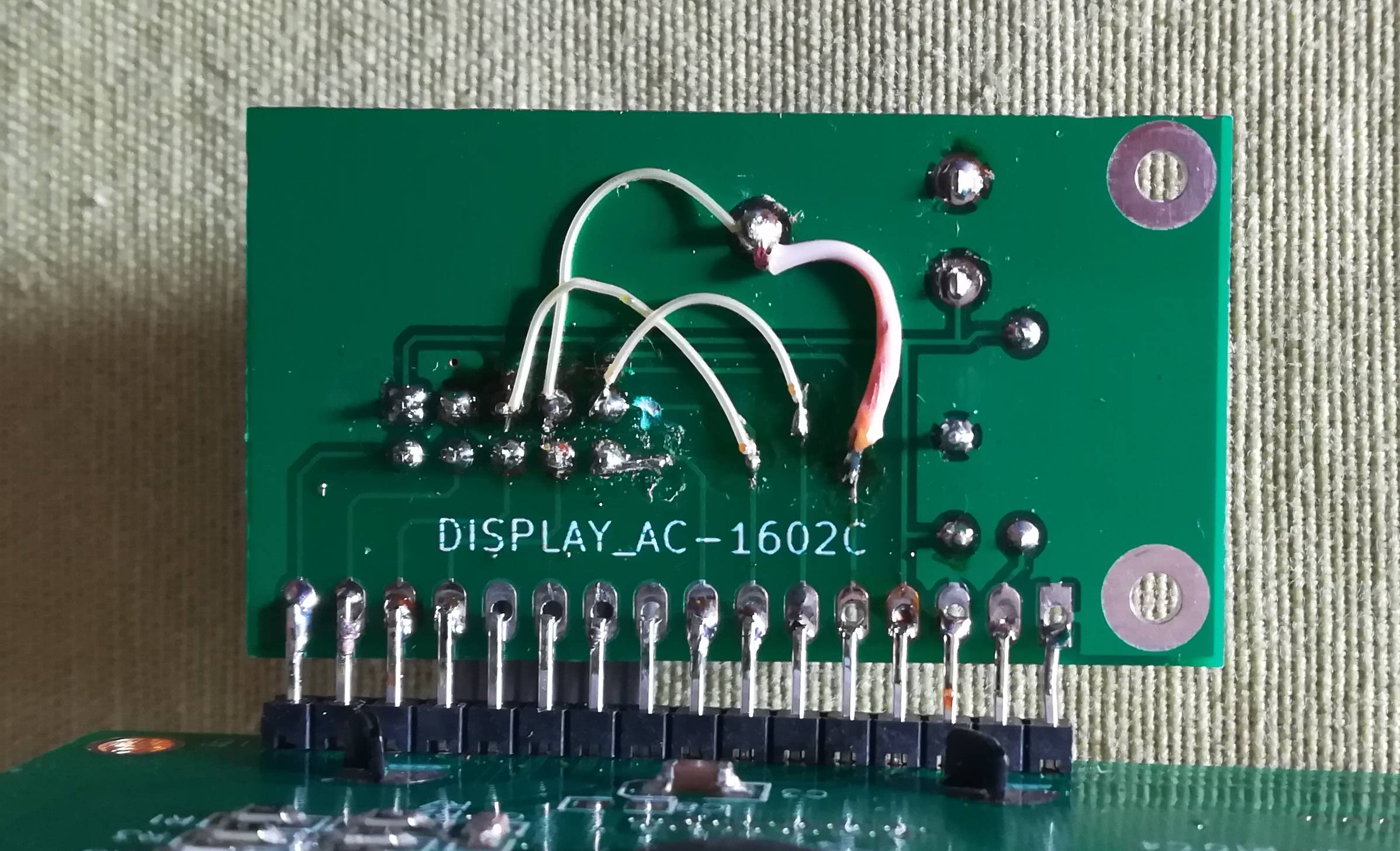
 |
 |
|
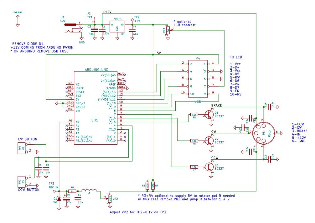
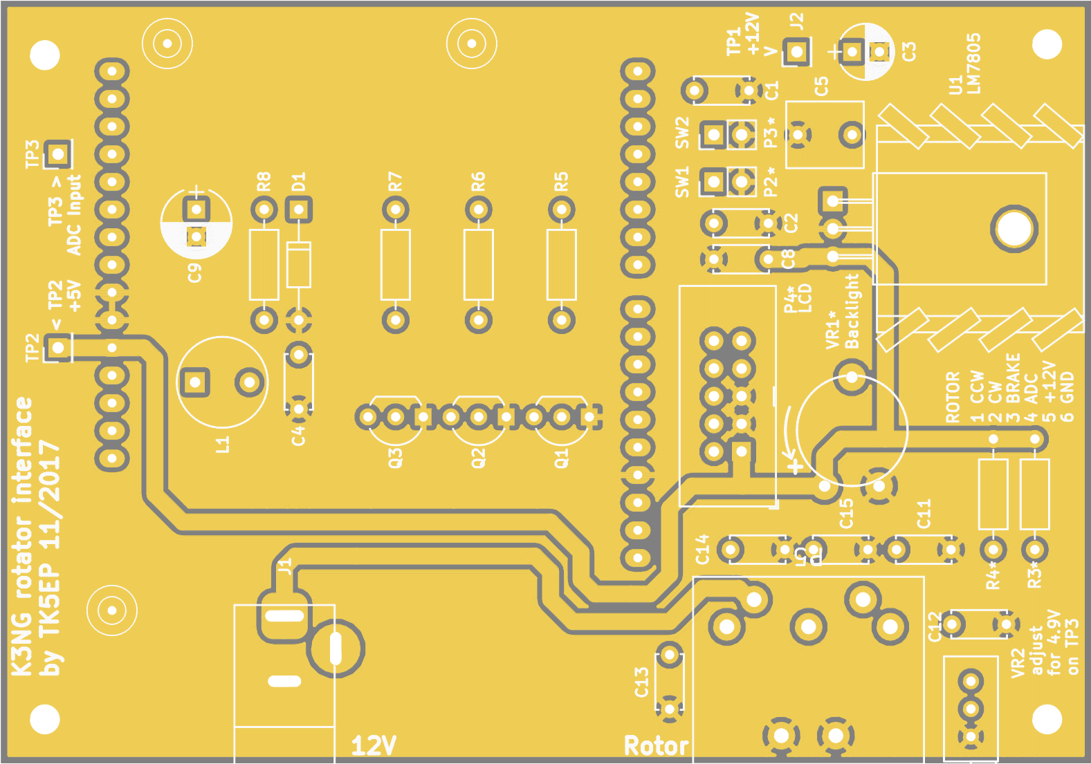
| Interface diagram (pdf) | Component fiting |
The control box has to be modified to be compatible with this interface. More informations can be found in my previous article HAM IV computer interface "à la K3NG"